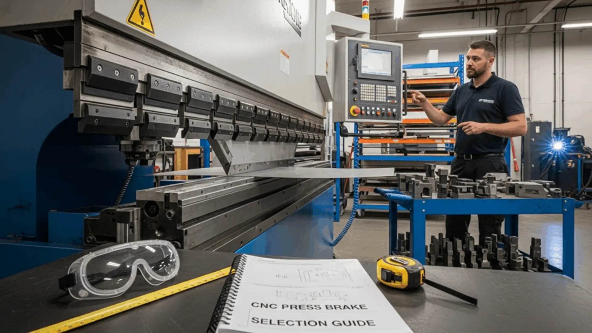
CNC Press Brake Operation Guide: From Parameters to Press Brake Tooling Selection
In the modern sheet metal fabrication industry, CNC press brake are indispensable due to their precision and efficiency. Mastering their operation requires a deep understanding of machine parameters, expertise in selecting appropriate press brake tooling, and process optimization. This comprehensive guide covers key parameters, bending tool types and their applications, process optimization techniques, and solutions to common challenges, complete with illustrative figure descriptions. Whether you’re a novice or an experienced technician, this guide will provide actionable insights to enhance your bending efficiency and product quality.
Core Parameters in CNC Bending Processes
Effective CNC bending hinges on precise control of critical parameters to meet design specifications. Below are the two primary parameters and their roles:
1. Pressure: The Key to Bending Precision
Pressure determines the force applied to the workpiece, directly affecting the bending angle and quality. The required pressure varies based on material type (e.g., stainless steel, aluminum, carbon steel), thickness, and bending angle. For example, bending a 1mm carbon steel sheet typically requires 50-60 tons of pressure, while stainless steel may demand higher force. Excessive pressure risks deforming the workpiece or damaging the tool, while insufficient pressure leads to inaccurate angles. Operators should consult the machine’s pressure-thickness chart or use empirical formulas (e.g., Pressure = Thickness × Material Factor × Bend Length) for precise settings.
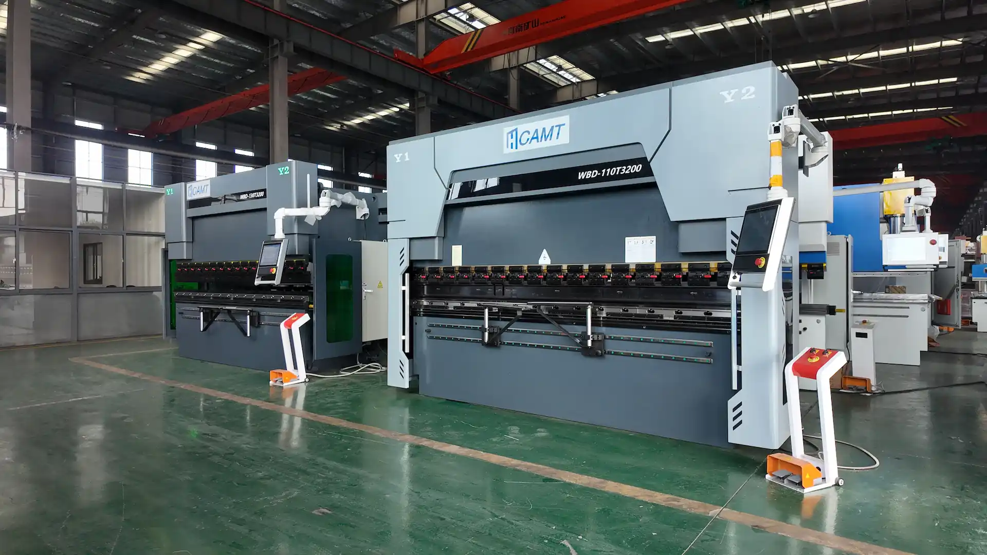
2. Worktable Length: Accommodating Workpiece Dimensions
The worktable length dictates the maximum workpiece size that can be processed. Common CNC press brakes offer worktable lengths from 1.5 to 4 meters, suitable for various sheet metal sizes. Selecting an appropriate worktable length ensures adequate support for the workpiece, preventing deformation due to overhang. For oversized workpieces, segmented bending may be necessary, requiring careful planning of the bending sequence to maintain accuracy. Proper pressure and worktable length settings lay the foundation for effective tool selection and process optimization.
Types of press brake tooling and Their Characteristics
Bending tools are critical to CNC bending, directly influencing precision and workpiece quality. Below are the main types of bending tools and their features:
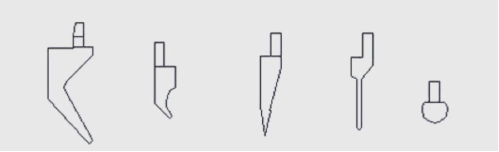
1. Straight Tool: Ideal for Simple Bends
The straight tool, with its flat edge, is the most commonly used bending tool, suited for straightforward, linear bends like standard 90-degree folds. Its robust structure ensures stability, making it ideal for thin sheets (0.5-2mm). However, straight tools are less effective for complex designs or situations requiring interference avoidance.
2. Small Bend Tool: Flexible for Clearance Needs
Designed with a narrow edge, the small bend tool excels in scenarios requiring clearance, such as bending near protrusions like rivet nuts or punched holes. It minimizes contact area to avoid interference, making it suitable for thin sheets (<1.5mm). However, its lower strength limits its use for thicker materials.
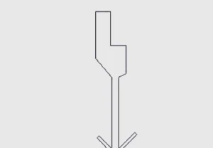
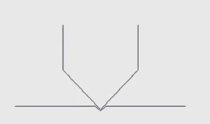
3. Goose-Neck Tool: Precision for Tight Spaces
The goose-neck tool, with its pointed edge, is perfect for high-precision bends in narrow or complex geometries. Its sharp tip allows for intricate clearance but compromises strength, making it unsuitable for sheets thicker than 1.5mm. Operators must control pressure to prevent tool wear or workpiece scratches.
4. Large Bend Tool: Handling Bigger Workpieces
Featuring a wider edge, the large bend tool is designed for larger workpieces or scenarios requiring significant clearance. Its high rigidity supports higher pressures, ideal for medium-thick sheets (2-6mm). However, it may reduce precision when used on smaller workpieces due to its larger contact area.
5. Custom press brake tooling: Tailored Solutions
For unique shapes or complex bending requirements, custom tools can be provided by suppliers. While these tools precisely match specific designs, their complex geometry often reduces rigidity, leading to shorter lifespans. When opting for custom tools, operators must balance shape, bending angle, and durability to ensure cost-effectiveness.
Applications and Clearance Strategies for Bending Tools
The choice of bending tool depends on workpiece design, material thickness, and process requirements. Below are common scenarios and corresponding clearance strategies, with figure descriptions for clarity:
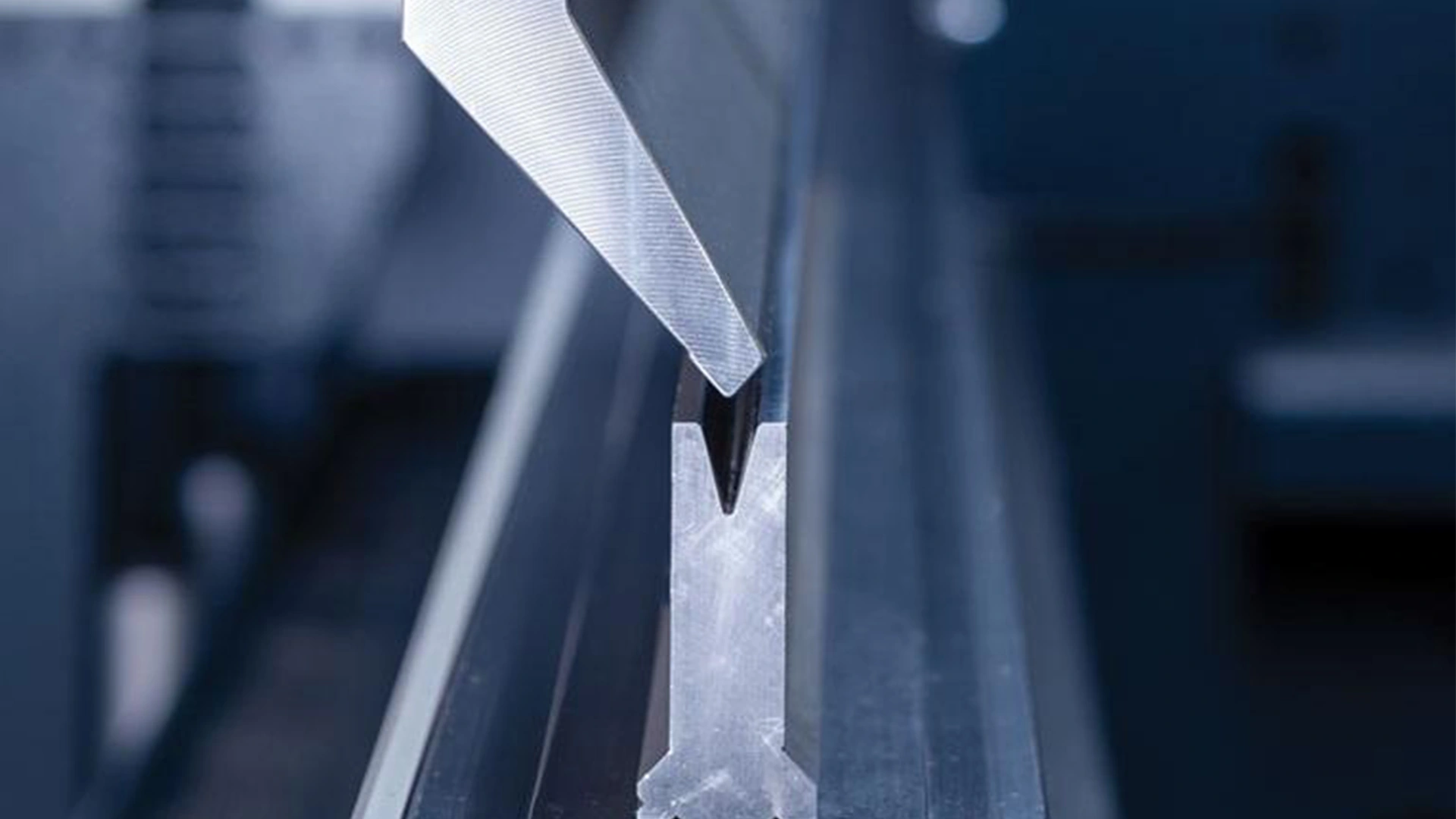
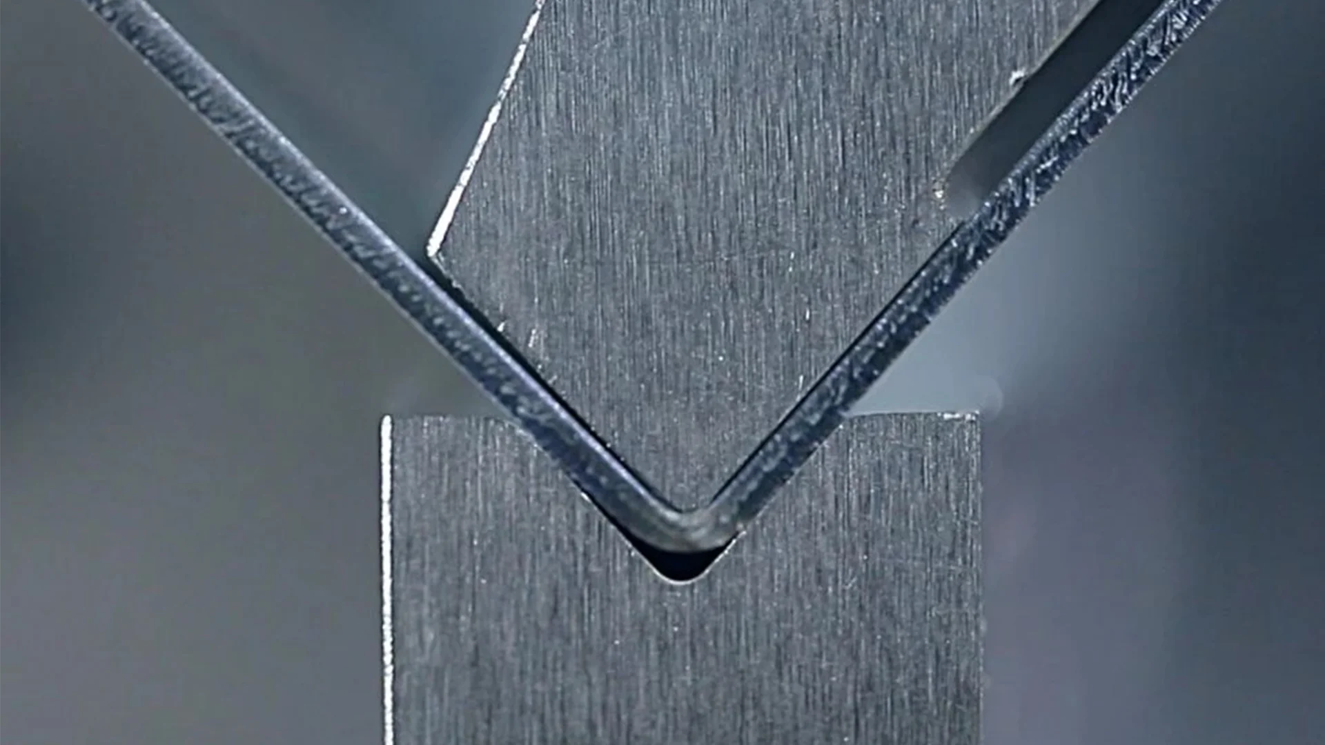
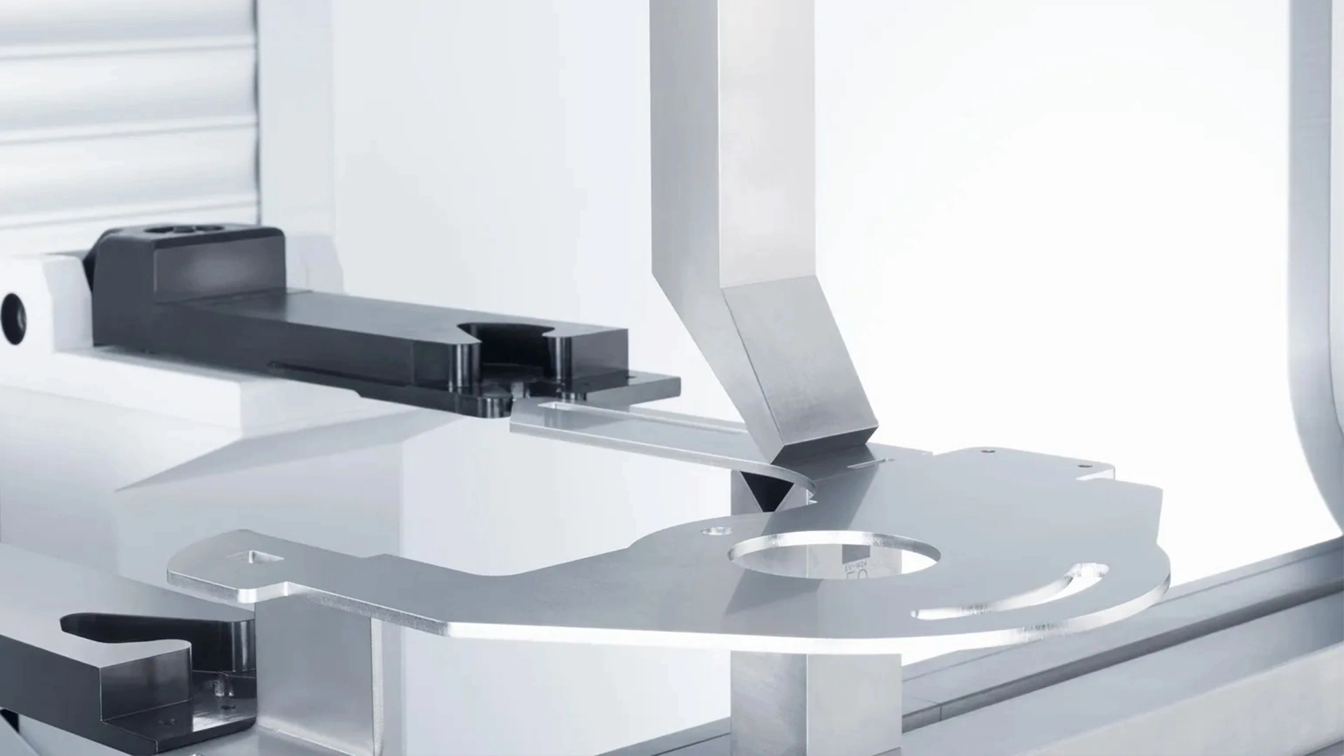
1. Simple Bending (No Clearance Required)
For workpieces requiring a single bend without interference, such as a 90-degree fold for cabinet panels, the straight tool is optimal. Its flat edge ensures clean, consistent bend lines, ideal for high-volume production of standard components.
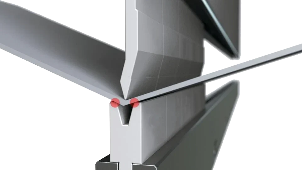
2. Complex Bending (Clearance Required)
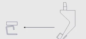
When workpieces feature protrusions or holes (e.g., rivet nuts or punched features), interference with the tool may occur. The following clearance strategies address these challenges:
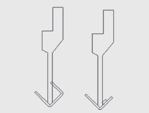
The left side shows interference caused by a rivet nut near the workpiece edge, while the right side depicts tool-workpiece collision during narrow-edge bending, highlighting the limitations of straight tools in complex structures.
Small Bend Tool Clearance: For minor interference near edges, the small bend tool’s narrow edge avoids obstacles, enabling precise bends.
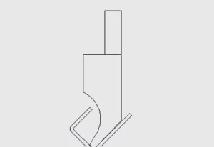
Shows a small bend tool with an 8mm-wide edge bending a 1mm thin sheet, avoiding a rivet nut protrusion, maintaining high bending accuracy.
Goose-Neck Tool Clearance: For narrow interference zones requiring high precision, the goose-neck tool is ideal but should be limited to thin sheets to avoid damage.
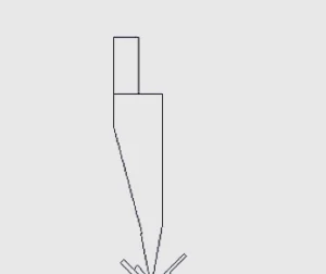
Depicts a goose-neck tool bending a 0.8mm thin sheet around a punched hole. Also includes an example of process adjustment, where riveting is scheduled after bending to avoid using a goose-neck tool on sheets thicker than 1.5mm, preventing tool damage.
Large Bend Tool Clearance: For larger interference areas or wide workpieces, the large bend tool provides ample clearance while maintaining accuracy.
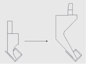
Illustrates a large bend tool with a 20mm-wide edge bending a 3mm medium-thick sheet, avoiding large protrusions like reinforcing ribs, ensuring stability and precision.
3. Multi-Step Bending and Process Optimization
In complex scenarios where single-step bending is insufficient, multi-step processes can be employed:
Pre-Creasing Process: Create a shallow crease along the bend line to guide subsequent bends, improving angle accuracy and reducing interference risks.
Shows a 0.2mm-deep crease created on a 2mm carbon steel sheet, guiding a subsequent 90-degree bend to avoid tool collisions.
Stepwise Bending: Bend the workpiece to 30 degrees initially, followed by a second bend to 90 degrees, minimizing misalignment in high-precision applications.
Depicts a stepwise bending process: the first step bends a 1.5mm stainless steel sheet to 30 degrees, followed by a second bend to 90 degrees along the crease, achieving an angle deviation of less than 0.5 degrees.
Dead-Edge Pressing: For fully flush edges (e.g., seals), bend to 30 degrees, then use a flat tool to press to zero clearance. If a punch press is available, prioritize it for superior dead-edge results.
Common Challenges and Solutions
Bending operations often encounter challenges that impact quality. Below are common issues and their solutions:
1. Workpiece-Tool Interference
Interference arises from complex designs or oversized workpieces. To mitigate:
Reorder bending sequences, placing interference-prone steps (e.g., riveting) after bending.
Use clearance tools like small bend or goose-neck tools for complex structures.
Ensure proper workpiece alignment on the worktable to avoid overhang or shifts.
2. Indentation Issues
Smaller die slots (e.g., 6-gauge) may cause visible indentations on thin sheets, affecting aesthetics and corrosion resistance. Solutions include:
Select die slots matching the sheet thickness (recommended slot width = 6× thickness).
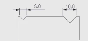
Compares a 6-gauge slot (6mm wide, suitable for 1mm sheets) and a 10-gauge slot (10mm wide, suitable for 1.5-2mm sheets), illustrating the impact of slot width on indentation.
Apply protective films or surface treatments (e.g., coating) to conceal minor indentations.
For high-aesthetic workpieces, use larger slots or adjust bend angles.
3. Bend Dimension Limitations
Bend dimensions are constrained by die slot width and bending coefficients. A slot width of 6× sheet thickness typically yields optimal results (e.g., 12mm slot for 2mm sheets). Operators should verify coefficients through trial bends and refer to machine manuals.
coating) to conceal minor indentations.
For high-aesthetic workpieces, use larger slots or adjust bend angles.
4. Tool Lifespan and Rigidity
Custom tools, while versatile, may have reduced rigidity, leading to faster wear. To extend tool life:
Avoid using goose-neck tools for thick sheets; opt for straight or large bend tools.
Regularly inspect tools for wear and perform timely maintenance or replacement.
Optimize workpiece designs to minimize reliance on complex tools.
Practical Tips for Optimizing Bending Processes
To boost bending efficiency and quality, consider these recommendations:
Early Process Planning: Optimize bend designs during the product development phase to reduce complex tool dependency.
Tool and Die Selection: Choose dies and tools based on material thickness and bend angles, aligning with empirical standards (e.g., 6× thickness for die slots).
Leverage CNC Features: Utilize advanced machine functions like auto-angle correction and pressure adjustment for complex tasks.
Quality Assurance: Verify bend accuracy with angle gauges and dimension tools after each bend, conducting trial runs for high-precision workpieces.
Conclusion and Call to Action
Mastering CNC bending requires a blend of technical expertise and practical experience. By fine-tuning parameters, selecting appropriate tools, and optimizing processes, operators can achieve superior bending results. This guide, complete with detailed figure descriptions, covers everything from pressure settings to clearance strategies and troubleshooting, equipping you to tackle any bending challenge. Start optimizing your bending operations today! Apply these insights to select the right tools and parameters for your workpieces, and explore our professional resources for the latest industry trends and technical support.

Metalworking specialist with 12 years of experience in sheet metal fabrication and press brake applications, certified by ASME.