Sheet Metal Design and Bending
Understanding the Basics of Sheet Metal Bending
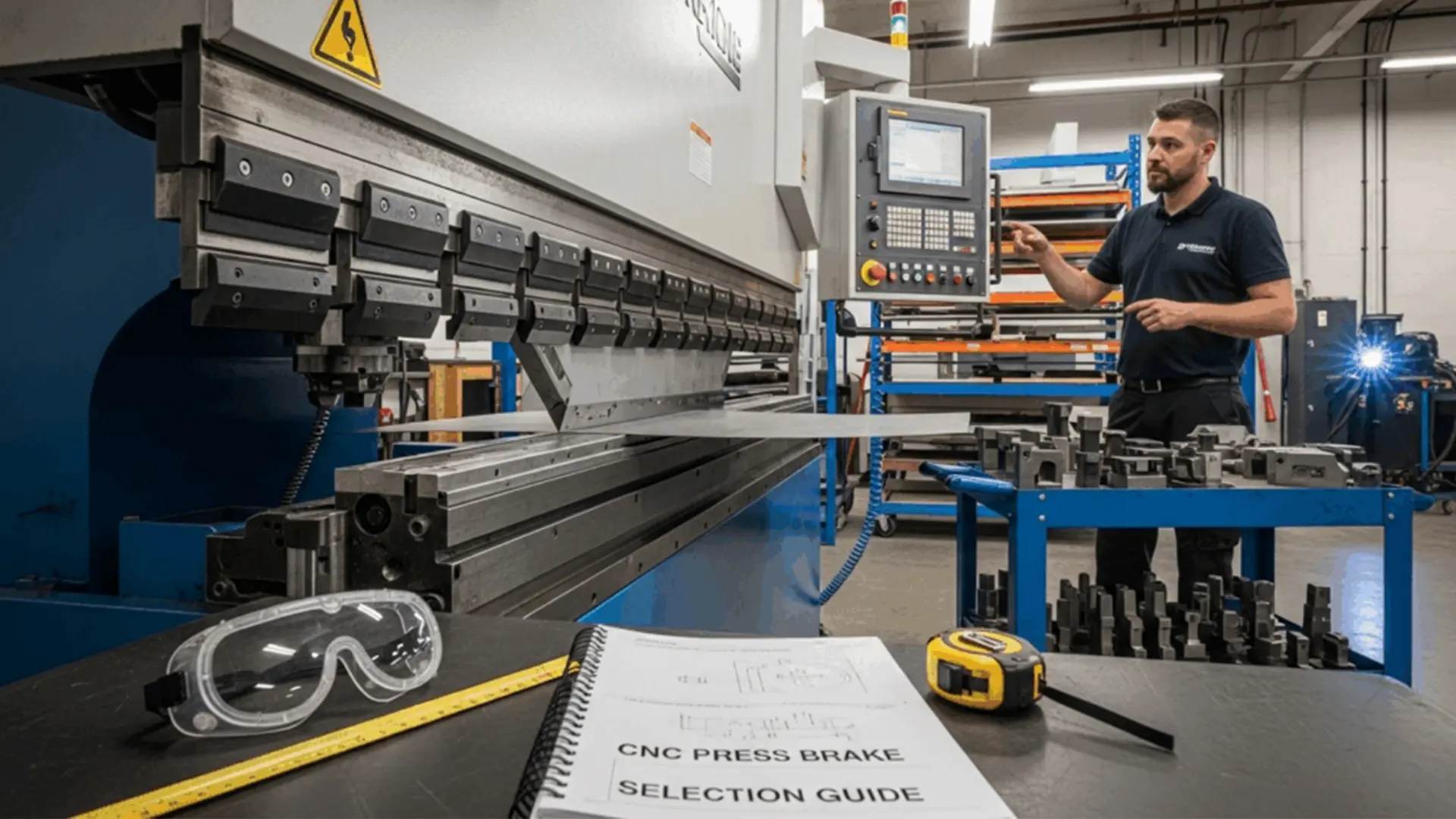
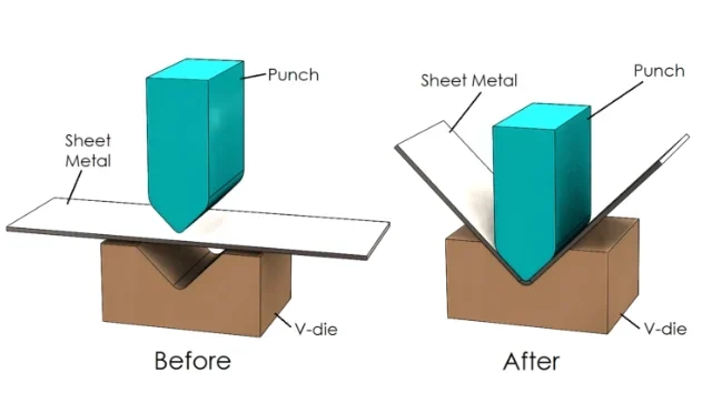
Sheet metal bending is a critical manufacturing process that involves applying pressure to a metal sheet through specialized equipment, causing it to deform into a predetermined angle or shape. This process transforms flat metal sheets into complex components used across industries like automotive, aerospace, and electronics. During bending, the metal undergoes a transition from elastic to plastic deformation under the pressure of the bending machine’s upper or lower die. This results in precise, durable shapes that meet specific design requirements.
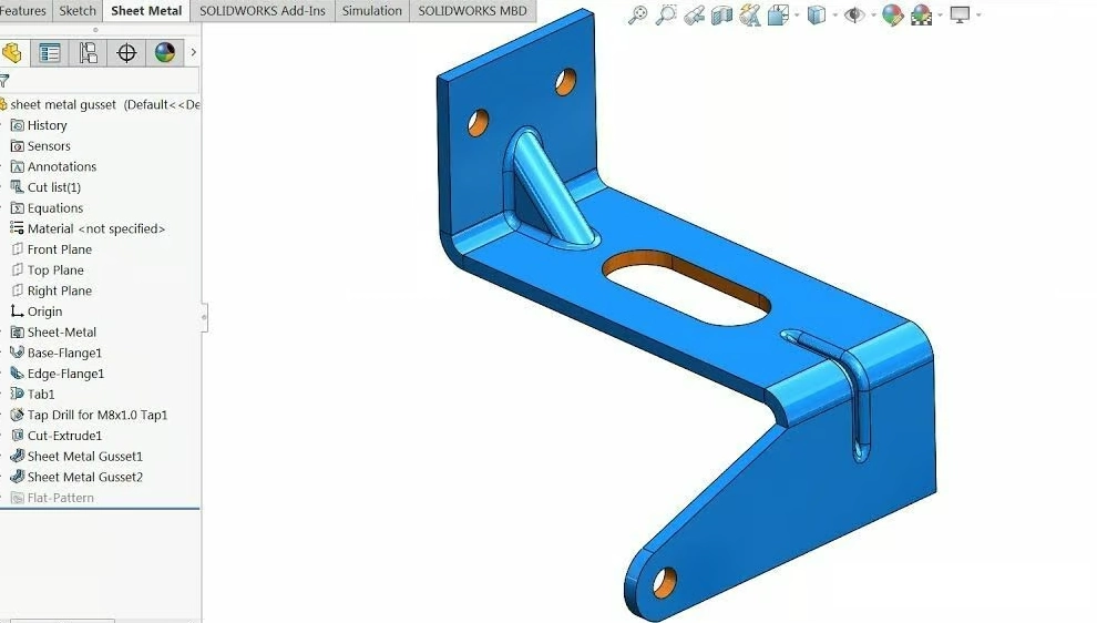
The bending process is foundational to sheet metal fabrication, enabling the creation of parts like enclosures, brackets, and structural components. By carefully controlling the bending parameters, manufacturers can achieve high precision and repeatability, ensuring components meet stringent quality standards. Understanding the mechanics of bending is essential for engineers and designers aiming to create functional and cost-effective sheet metal parts.
Working Principles of Bending Machines and Common Techniques
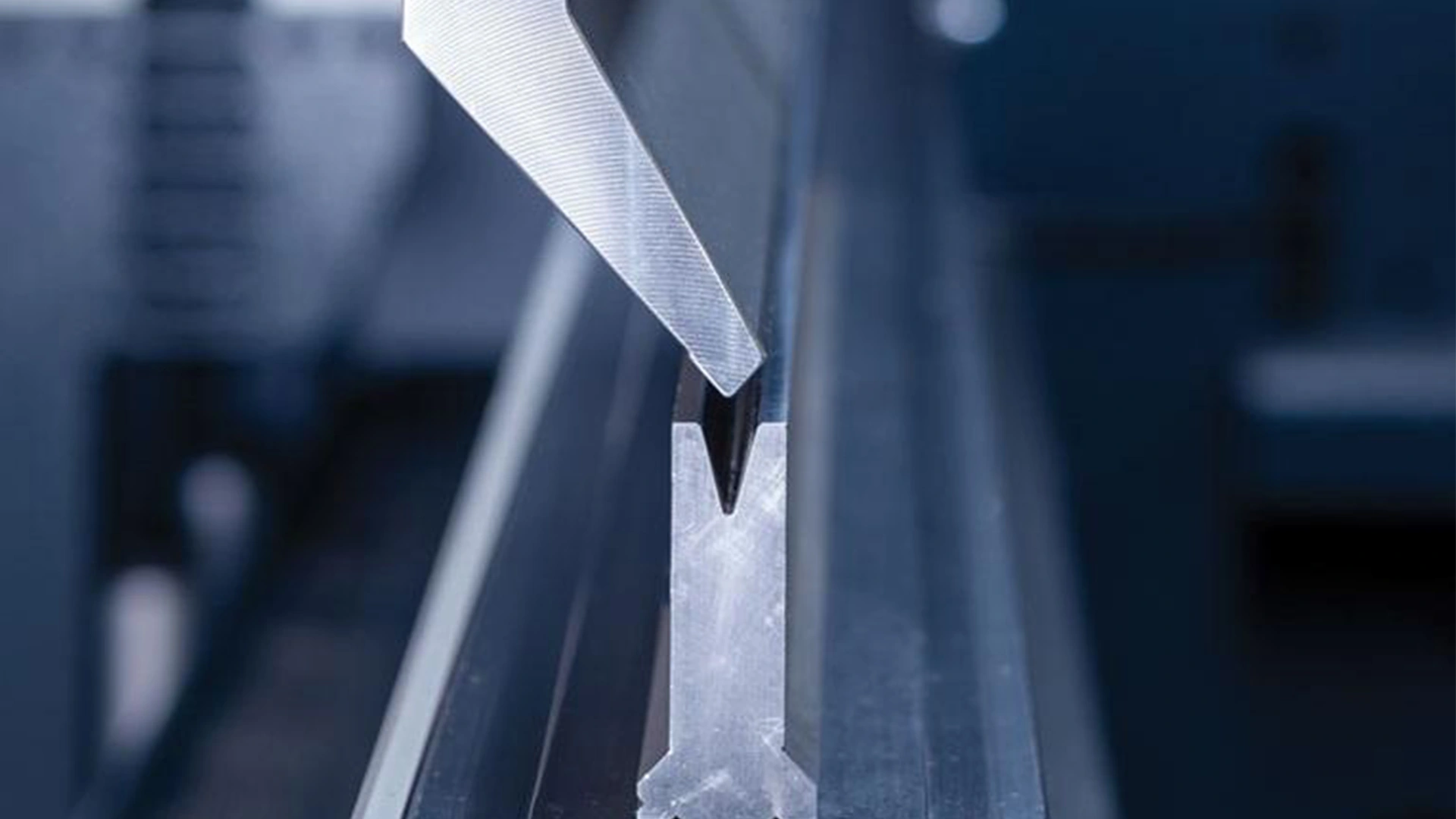
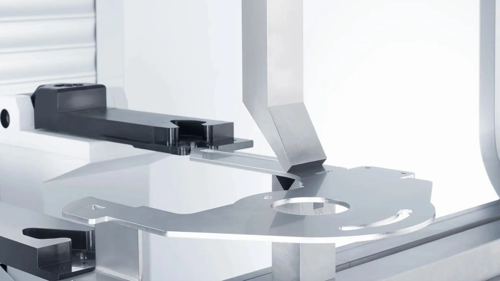
Bending machines are the cornerstone of sheet metal bending, utilizing hydraulic or mechanical systems to drive the relative motion of the worktable and dies. The upper and lower dies work together to shape the metal sheet into the desired form. The machine’s precision and versatility make it suitable for a wide range of applications, from simple brackets to intricate assemblies.
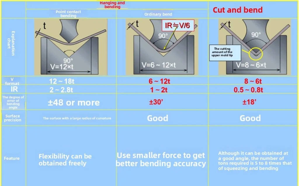
There are three primary bending techniques used in sheet metal fabrication:
Free Bending: This method offers flexibility and is ideal for large or simple components. It involves minimal contact between the die and the workpiece, allowing for quick setup and adaptability to various shapes.
Three-Point Bending: Known for its high precision, this technique uses three contact points to control the bending process, making it suitable for complex parts with tight tolerances.
Correction Bending: This method is used for specialized components with unique cross-sectional shapes or stringent requirements. It involves additional adjustments to achieve the desired outcome.
Each technique has its advantages, and the choice depends on the part’s complexity, material properties, and production goals. By selecting the appropriate method, manufacturers can optimize efficiency and quality.
CNC Bending Machines: Features and Applications
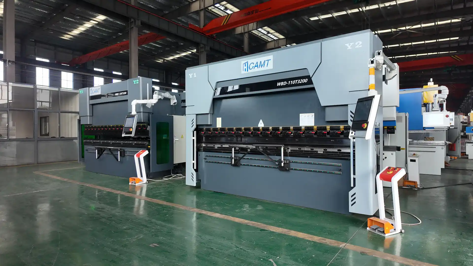
CNC (Computer Numerical Control) bending machines represent the pinnacle of modern sheet metal processing, offering unparalleled precision, efficiency, and automation. These machines are equipped with multiple CNC axes, including:
Y1 and Y2 Axes: Control the vertical movement of the ram, ensuring consistent bending angles.
V Axis: Manages the crowning system to compensate for machine deflection, maintaining straightness in long parts.
Backgauge and Servo-Follower Systems: Position the sheet accurately and support it during bending, enhancing repeatability.
CNC bending machines excel in high-volume production and complex geometries, making them indispensable in industries requiring precision, such as aerospace and medical device manufacturing. Their programmable nature allows for quick reconfiguration, reducing setup times and enabling flexible production. Optional features, such as advanced tooling systems or robotic integration, further enhance their versatility, making CNC bending machines a cornerstone of modern manufacturing.
Factors Affecting Bending Accuracy
Bending accuracy is a critical metric in sheet metal fabrication, directly impacting the functionality and aesthetics of the final product. Several factors influence the precision of the bending process:
Machine Precision: The accuracy of the bending machine, including its hydraulic or servo-driven systems, plays a significant role. Regular maintenance and calibration are essential to ensure consistent performance.
Tooling Design and Quality: The precision of the upper and lower dies, as well as their alignment, affects the bending outcome. High-quality tooling reduces errors and ensures uniformity.
Material Properties: The type, thickness, and grain direction of the metal sheet influence bending behavior. For example, stainless steel and aluminum respond differently to bending forces due to variations in ductility and strength.
Operator Expertise: Skilled operators can optimize process parameters, such as bending speed and pressure, to achieve better results.
Environmental Factors: Temperature and humidity can affect material behavior and machine performance, requiring stable production conditions.
To achieve high bending accuracy, manufacturers must develop robust process plans, train operators, and use advanced equipment to account for these variables. By addressing these factors, businesses can ensure consistent, high-quality results.
Sheet Metal Unfolding: Principles and Calculations
Sheet Metal Unfolding: Principles and Calculations
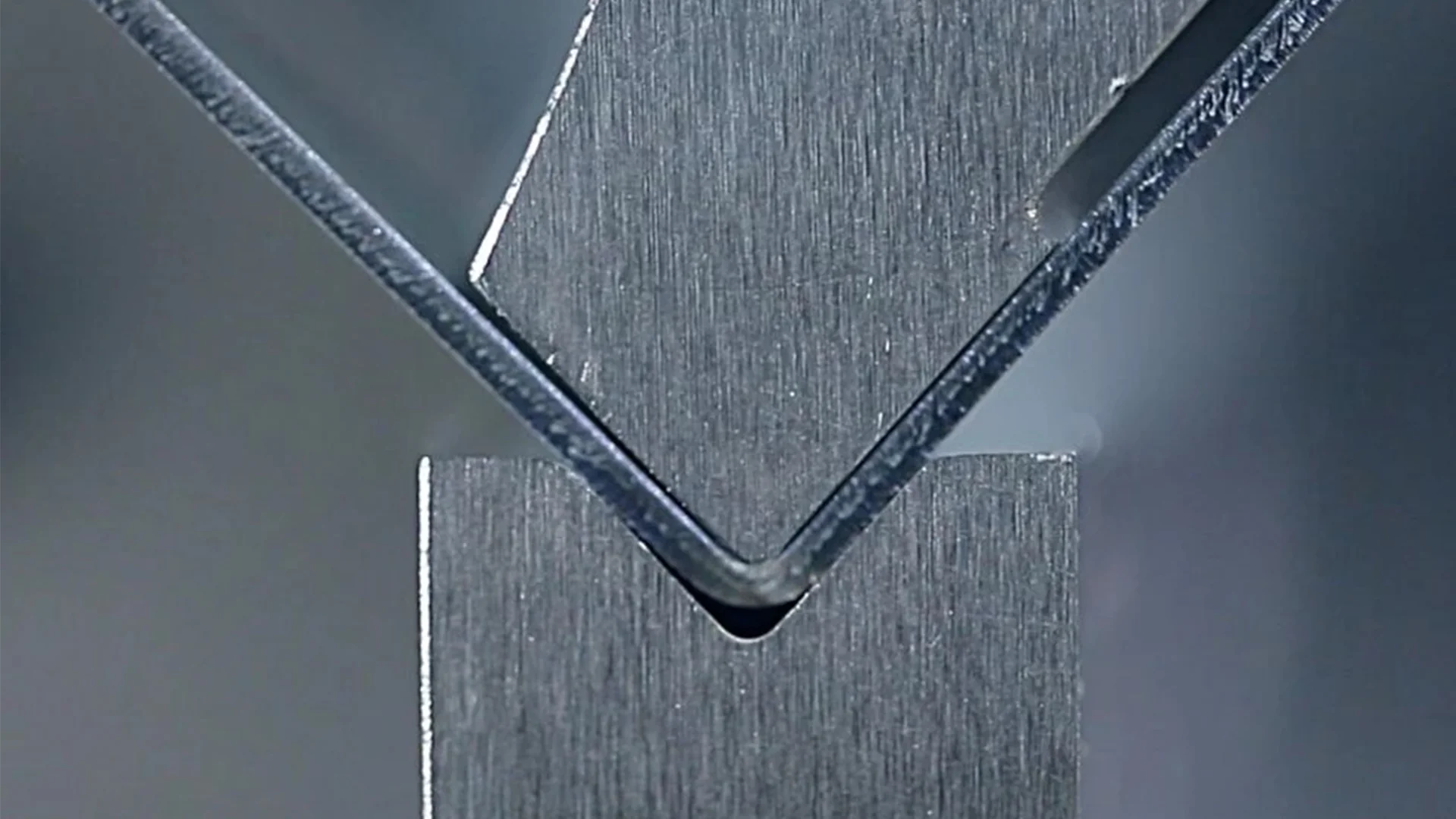
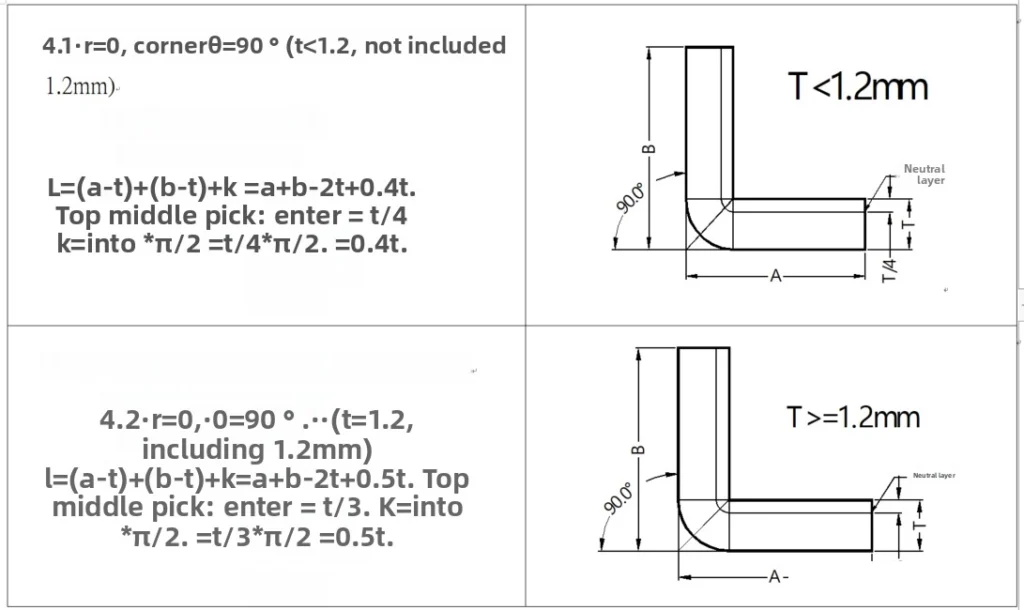
Unfolding is a critical step in sheet metal design, determining the flat pattern of a part before bending. During bending, the outer layer of the sheet experiences tensile stress, while the inner layer undergoes compressive stress. The neutral axis, located between these layers, remains unstressed and maintains its length throughout the bending process. The position of the neutral axis, denoted by λ (the distance from the inner surface), shifts depending on the bending radius and angle. A larger radius or smaller angle positions the neutral axis closer to the sheet’s centerline, while a smaller radius or larger angle shifts it inward.
Understanding the neutral axis is key to accurate unfolding calculations. The basic formula for unfolding length is:
Unfolded Length = Inner Length + Inner Length + Compensation
The compensation factor accounts for material stretching and compression during bending, ensuring the flat pattern accurately reflects the final bent shape. Precise calculations prevent material waste and ensure components fit perfectly during assembly.
Example Illustration
Consider a sheet metal part with a 90-degree bend, a 5mm bending radius, and a 2mm sheet thickness. The neutral axis position (λ) is calculated based on material properties and bending parameters. Using industry-standard tables or software, the compensation value is determined, and the unfolded length is calculated as the sum of the inner lengths plus the compensation. This process ensures the flat pattern aligns with the final bent geometry, minimizing errors in production.
By mastering unfolding calculations, designers can create accurate flat patterns, streamline production, and reduce costly rework. Tools like CAD software or specialized unfolding calculators can further enhance accuracy, especially for complex parts with multiple bends.

Metalworking specialist with 12 years of experience in sheet metal fabrication and press brake applications, certified by ASME.