Working Principle and Characteristics of Plate Rolling Machine
Mastering Metal Curvature: The Plate Rolling Machine's Innovative Design and Operational Edge
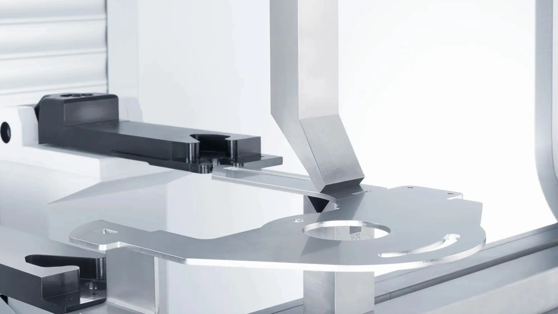
In the dynamic field of metal fabrication, particularly within steel drum production, the plate rolling machine emerges as an indispensable tool that converts flat sheets into precise cylindrical forms. These machines are the unsung heroes behind the creation of robust containers used for transporting liquids, powders, and hazardous materials across global supply chains. Whether you’re optimizing a factory floor or simply curious about industrial mechanics, grasping how this equipment functions can illuminate pathways to enhanced efficiency and quality. Through its sophisticated bending techniques and adaptable features, it supports seamless transitions to welding processes, reducing material waste and ensuring structural integrity. Let’s explore the intricacies of its operations, from fundamental principles to specialized applications, while highlighting why it continues to evolve in modern manufacturing.
Imagine a production line where steel sheets, typically 0.6 to 2.0 mm thick, are sheared, edged, and then rolled into tubes with diameters around 560 mm for standard 200-liter drums. This transformation relies on the machine’s ability to apply uniform pressure, leveraging friction to guide the material through curved paths. In environments favoring automation, rolling dovetails with welding for streamlined output, whereas standalone units offer versatility in semi-automated setups. The result? Drums that comply with rigorous standards like those from ASTM or ISO, capable of withstanding pressures up to 2 bar without failure.
From an operational standpoint, efficiency metrics are telling: Advanced models can handle up to 15 sheets per hour in batch modes, cutting labor costs by 40% compared to older methods. This isn’t mere machinery—it’s a blend of physics and engineering that minimizes defects such as seam mismatches or surface imperfections, which could otherwise lead to recalls or safety issues.
The Core Working Principle of Plate Rolling Machines
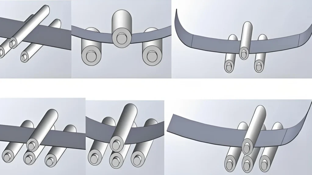
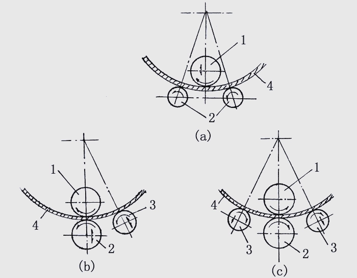
Fundamentally, plate rolling machines operate by deforming metal sheets through rotational force and compression, categorized primarily into three-roll and four-roll configurations, with three-roll further split into symmetric and asymmetric variants.
Consider the symmetric three-roll setup first: It consists of an upper roller positioned symmetrically between two lower rollers. The upper one adjusts vertically to dictate the bend radius, while the lowers, powered by electric motors and gear reducers, rotate in unison to propel the sheet forward. As the material is sandwiched and pressed, three-point contact induces bending, with friction ensuring smooth advancement and even curvature across the length.
This design excels in producing cylinders for steel drums, accommodating widths up to 4 meters in industrial scales. However, a notable quirk is the residual straight edges at the sheet ends—roughly half the span between lower rollers—necessitating additional pre-bending steps to achieve full roundness.
Turning to the asymmetric three-roll: Here, the upper roller hovers above one lower, with a side roller angled offset. This arrangement allows for pre-bending the edges right from the start, dramatically reducing flat segments to less than double the plate thickness. The process involves feeding the sheet, clamping it via lower adjustments (up to the max thickness capacity), and positioning the side roller along its incline for targeted pressure. Powered rotation then curves the material, and a simple reversal or reorientation completes any unfinished sections.
The edge here—pun intended—is in precision: For drum bodies requiring tight tolerances, this minimizes post-processing, potentially boosting throughput by 25%. Drive mechanisms mirror the symmetric type, but the side roller’s passive nature adds flexibility for varied shapes like cones or ovals.
Elevating to four-roll machines: Building on asymmetric principles, an additional side roller eliminates the need for sheet flipping. Both sides collaborate to curl edges simultaneously, making it a go-to for high-volume, automated lines. All rollers are typically driven, often hydraulically for plates thicker than 10 mm, though drum production favors lighter-duty electric variants.
In practical terms, operators set parameters like roller gap (e.g., 1.2 mm for 1 mm steel) and speed (4-6 m/min) to match material properties. Over-bending by 8-15% accounts for elastic recovery, ensuring the final diameter hits specs like 571 mm outer for standard barrels. Power options range from manual for prototypes to CNC-integrated for mass production, where software simulates bends to preempt errors.
To compare types succinctly:
- Symmetric Three-Roll: Budget-friendly and straightforward, ideal for basic drum rolling; drawback: extended straight edges requiring manual fixes.
- Asymmetric Three-Roll: Superior edge control, versatile for custom diameters; minor con: occasional material repositioning.
- Four-Roll: Streamlined for speed and accuracy in automation; higher initial investment but lower long-term costs via reduced labor.
Across these, common threads include hardened rollers (Rockwell hardness 50-60) to resist wear and variable speed controls for materials from carbon steel to stainless alloys.
Detailed Deformation Dynamics in Plate Rolling Operations
Deformation isn’t a singular event but a phased progression: elastic, elasto-plastic, and fully plastic, each governed by material stress-strain behaviors.
The journey begins elastically: Initial low-moment forces keep internal stresses below the yield limit (σs, typically 245-345 MPa for drum-grade steel), allowing the sheet to snap back unchanged upon release—like flexing a sturdy ruler without creasing it.
As moments intensify, the elasto-plastic phase ensues. Outer fibers surpass yield, deforming permanently, while inner ones remain resilient. This creates a stress profile: tensile on the convex side, compressive on the concave, with a neutral plane where stress nullifies (curvature radius ρσ).
Culminating in pure plastic deformation, the entire section yields, locking in the shape with negligible rebound if properly over-rolled. For drums, this stage is critical to counter springback—often 12-18% in cold-rolled high-strength sheets—via empirical adjustments.
Visualizing stress: Tangential forces transition from pull to push across the thickness, zeroing at the neutral stress layer. Strain follows suit, null at the neutral strain layer (ρε). In mild bends, both layers align at midpoint (r + t/2, r inner radius, t thickness). Intense deformation shifts them inward, with stress layer moving farther (ρσ < ρε). Practical formula for strain neutral: ρε = r + x*t, x ≈ 0.33 for moderate drum curvatures.
This knowledge informs blank calculations: Underestimate, and overlaps fall short; overestimate, waste ensues. Advanced simulations using finite element methods (FEM) refine this, slashing prototyping costs by 35% in R&D phases.
Key influencers on deformation:
- Material Traits: Higher ductility (e.g., elongation >20%) eases bending; brittleness risks fractures.
- Thickness Variations: Thinner sheets (0.7 mm) demand gentler pressures to avoid rippling.
- Roller Specs: Larger diameters distribute force, yielding smoother surfaces.
- Environmental Factors: Room temperature cold rolling for drums; elevated heats for thicker gauges to lower yield points.
A phased overview table:
Phase | Stress Condition | Key Features |
Elastic | Below σs | Fully reversible, no lasting change |
Elasto-Plastic | Partial above σs | Hybrid deformation, moderate springback |
Plastic | Fully above σs | Permanent form, requires compensation for minimal rebound |
Understanding these phases empowers operators to troubleshoot issues like buckling or uneven thickness reduction.
Common Structural Elements of Plate Rolling Machines
The anatomy of a plate rolling machine directly influences its robustness and output quality. Essential parts include rollers for direct bending, frames for structural support, drives for motion, and controls for oversight.
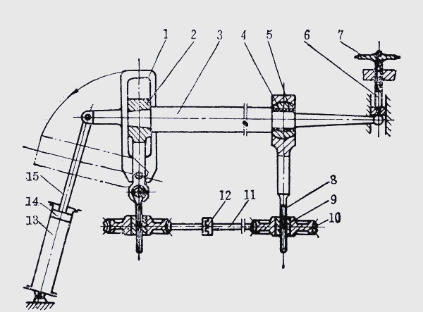
In typical setups for steel drum applications—often mid-sized symmetric three-roll—dual frames anchor lower roller bearings, with shaft extensions linking to motors via gears for synchronized rotation. Directional control comes via handles or switches for forward/reverse operations.
Upper roller mechanics feature worm-driven wheels connected to nuts and screws for vertical movement, enabling radius tweaks. Tilt capabilities arise from clutch mechanisms that decouple one side, allowing angled positioning for tapered rolls.
For material extraction, pneumatic or hydraulic cylinders actuate pistons to swing movable frames outward, as depicted in standard blueprints. Conical shaft ends and ball-shaped supports facilitate bearing disengagement without drops, while handwheels secure positions during maintenance.
Broader component insights:
1.Rollers: Core bending agents, forged from alloy steel, often crowned slightly to compensate for deflection under load.
2.Frames and Bases: Heavy-duty welded assemblies, sometimes with dampers to absorb vibrations in high-speed runs.
3.Drive Systems: Electric motors (7.5-75 kW) paired with reducers; variable frequency drives (VFDs) for speed modulation.
4.Adjustment Mechanisms: Mechanical screws for small units, hydraulics (150-250 bar) for industrial.
5.Control Interfaces: From basic panels to touchscreen CNC, integrating sensors for real-time feedback on force and alignment.
These elements ensure machines fit seamlessly into drum lines, with footprints as compact as 3m x 1.5m for portability.
Advanced Rolling Integrations in Automatic Seam Welding Systems
Within automated seam welding for steel drums, the rolling module serves as a vital pre-weld step, tailored for diverse sheet dimensions to feed efficient joining.
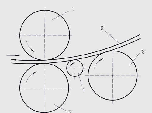
A standard three-roll configuration features upper, lower, and rear rollers, all driven from a single source for uniform peripheral speeds. The upper-lower pair maintains a subtle 0.25 mm separation, with the lower spring-supported to accommodate sheets over that thickness, curbing noise and extending bearing longevity to 70,000 hours.
Rear roller positioning adapts to sheet specs, tension, and target diameters, incorporating over-curvature to offset rebound—ensuring 75-100 mm end overlaps for robust seams. A passive sliding roller guides leading edges to the forming zone, mitigating minor distortions without active power.
This integration accelerates lines to 10-15 units per minute, with modular designs allowing quick swaps for maintenance downtime under 30 minutes.
Historical Context and Emerging Trends in Plate Rolling Technology
Tracing back to early 19th-century manual benders, plate rolling advanced with steam power in the industrial revolution, then hydraulics in the mid-20th. Today’s digital controls mark a leap, with IoT enabling remote monitoring.
Forward-looking: Machine learning algorithms predict wear, reducing failures by 25%. Electric-hydraulic hybrids cut energy by 20%, supporting eco-friendly mandates. Additive manufacturing for custom rollers promises faster prototyping.
Broadening Horizons: Plate Rolling Machine Applications Outside Steel Drums
Versatility extends to aerospace for fuselage sections, shipbuilding for curved hulls, construction for arched supports, and energy for wind turbine towers or pressure vessels. In automotive, it’s for exhaust pipes; in HVAC, ducting.
Each adapts principles: Thicker plates (20+ mm) for towers use four-roll heavies, while thin alloys for aero demand precision asymmetrics.
Best Practices for Maintenance and Safety in Plate Rolling Operations
Routine care: Daily visual checks, weekly greasing, monthly alignment verifications using lasers. Annual overhauls include roller resurfacing.
Safety essentials: Interlocked guards, emergency pull cords, operator training on pinch hazards. PPE like gloves and helmets mandatory; compliance with OSHA-like standards prevents incidents.
Troubleshooting: Warped rolls from overload—stick to capacity (e.g., 10 mm max for mid machines); uneven bends from misalignment—recalibrate quarterly.
Benchmarking Plate Rolling Against Other Forming Methods
Relative to press brakes: Rolling suits long curves efficiently; brakes excel in sharp angles but lag on cylinders.
Hydroforming offers complex shapes sans tools but at premium costs. Rotary draw bending for tubes, not sheets.
Comparative table:
Technique | Advantages | Drawbacks |
Plate Rolling | High-volume curves, cost-effective | Primarily cylindrical |
Press Brake | Multi-angle versatility | Time-intensive for rounds |
Hydroforming | Tool-free complexity | High setup expense |
Ultimately, the plate rolling machine’s fusion of reliable principles and adaptable characteristics propels it as a cornerstone in fabrication, driving innovations from everyday drums to cutting-edge structures.

Metalworking specialist with 12 years of experience in sheet metal fabrication and press brake applications, certified by ASME.