CYPCUT Laser Cutting Software Operation Manual
Introduction to the CYPCUT Laser Cutting Software
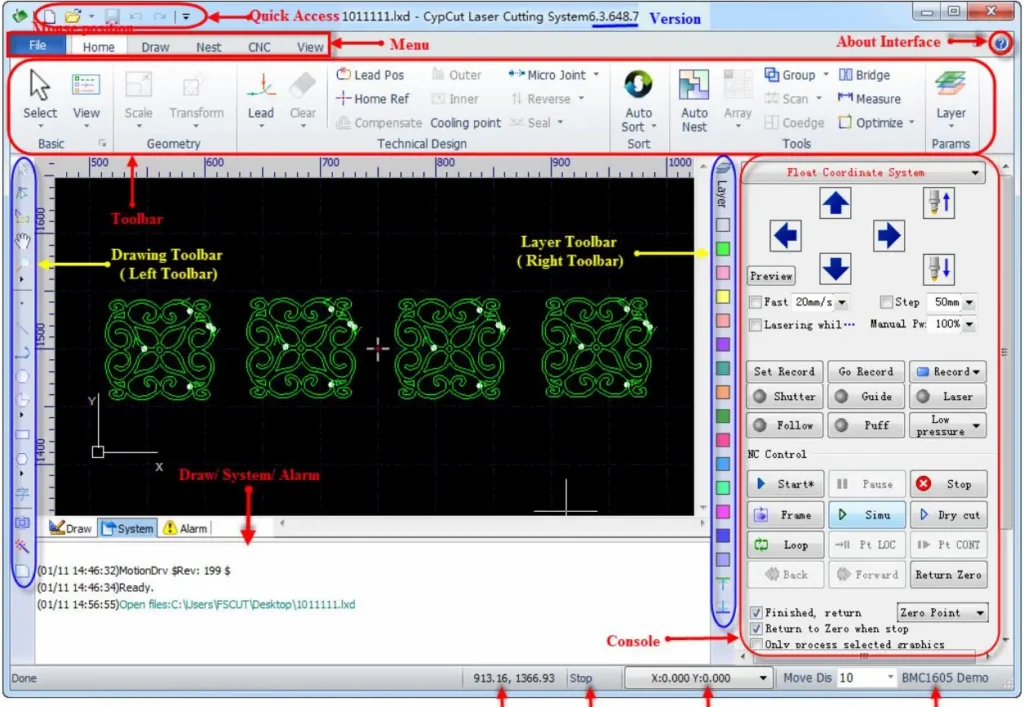
The CYPCUT laser cutting software, developed by Friendess (also known as Bochu or FSCUT), is a powerful and user-friendly control system specifically designed for fiber laser cutting machines. This intuitive platform streamlines the entire process from design to execution, making it ideal for both beginners and experienced operators in the laser cutting industry. The interface features a clean, ribbon-style layout that enhances productivity by providing quick access to essential tools and functions.
Key components of the CYPCUT interface include:
- Drawing Board: The central black workspace where graphics are displayed and edited. A white frame outlines the machine’s working area, with adjustable grids and rulers that scale dynamically during zooming.
- Menu Bar and Toolbar: Located at the top, the ribbon-style toolbar is divided into tabs like ‘Home’, ‘Draw’, ‘Nest’, ‘CNC’, and ‘View’. Each tab offers buttons for common operations, with drop-down menus for advanced options. For instance, the ‘Home’ tab includes tools for lead lines, sorting, and optimization.
- Quick Access Bar: At the top-left, for file management (new, open, save) and undo/redo functions.
- Drawing Toolbar: On the left side, with mode switches (selection, node editing, sequence editing, pan, zoom) and graphic insertion tools (points, lines, circles, etc.).
- Technique Toolbar: On the right, featuring layer management with 17 color-coded buttons to assign and configure cutting parameters.
- Control Panel (Console): The right rectangular area for coordinate system selection, manual controls, machining operations (start, pause, simulate), process settings, and production counters.
- Status and Information Bars: At the bottom, displaying drawing commands, system messages (color-coded for errors, alarms, etc.), alarms, graphic info, cursor/laser positions, and fine-tuning controls.
This setup ensures seamless navigation, allowing users to focus on creating precise cuts for sheet metal, tubes, and other materials. For optimal performance, ensure the software is run as an administrator on Windows systems and disable antivirus during installation to avoid conflicts.
Basic Operation Procedures in CYPCUT Laser Cutting Software
Mastering the basic operations in CYPCUT is essential for efficient laser cutting workflows. Below, we break down the key procedures, including step-by-step guides and tips drawn from official manuals and practical usage.
1. Coordinate and Parameter Input for Precise Drawing
In scenarios requiring exact positioning, CYPCUT supports direct coordinate entry. The format is “<X coordinate>,<Y coordinate>” (e.g., “100,100”), displayed in blue for visibility. This method complements mouse-based drawing and is available in most graphic creation tools.
Example: Drawing a rounded rectangle (300mm long, 200mm wide, 25mm fillet radius):
- Click the rounded rectangle icon in the left toolbar. The prompt says “Please specify the starting point.”
- Enter “0,0” and press Enter. Now prompted for the diagonal point.
- Enter “300,200” and press Enter. Prompted for “Please specify fillet radius or [Chamfer(F)]:”
- Enter “25” and press Enter to complete.
This precision input ensures accuracy in complex designs, reducing errors in laser cutting paths.
2. Automatic Snap (Adsorption) Feature
During drawing, CYPCUT’s auto-snap function magnetically aligns the cursor to grids, key points on graphics, or boundaries, enhancing speed and precision. To disable it:
- Go to ‘File’ > ‘User Parameters’ > ‘Drawing’ tab.
- Uncheck “Keypoint automatic adsorption.”
- Adjust snap precision in the same dialog for finer control.
This feature is particularly useful for aligning elements in intricate patterns, but disabling it allows for freehand adjustments when needed.
3. Graphic Drawing Tools
CYPCUT offers a robust suite of drawing tools in the left toolbar, similar to CAD software, for creating standard shapes. From top to bottom: isolated point, line, polyline, circle, arc, rectangle, polygon, text, and standard parts. The ‘Draw’ menu provides additional options.
Standard Graphic Drawing
- Basic shapes like points, lines, polylines, circles, and rectangles are straightforward—click to start and define endpoints or radii.
- Advanced circle options: Under ‘Draw’ > ‘Circle’ dropdown, “Replace circle positioning hole with isolated point” converts small circles to points for efficiency; “Replace with circle” refines near-circular shapes for fly cutting.
- Polygon variations: Click the triangle below the polygon button for rounded rectangle (draw rectangle first, then set radius via cursor or input), regular polygon (specify sides 3-100, rotatable), or star (sides define points, e.g., 6 for hexagram).
- Additional shapes: In ‘Draw’ > ‘Rectangle’ dropdown, “Obround” adds semicircles to a rectangle’s ends, creating a racetrack shape.
These tools enable quick prototyping of parts for laser cutting applications.
Text Input
Click the text button on the left toolbar, then click the insertion point. New text is auto-selected for editing. A ‘Text’ tab appears in the toolbar for modifying content, style, size, etc. Convert text to curves for cutting paths, but note that post-conversion edits are unavailable—design fully before converting.
4. Standard Parts Library
For common components, click the standard parts button on the left toolbar. Select a part type (e.g., gears, flanges) and configure parameters in the subsequent dialog. This saves time on repetitive designs, ensuring consistency in laser-cut parts.
5. Measurement Tools
To measure distances:
- Click ‘Home’ > ‘Tools’ > ‘Measure’.
- Select the first point; a guide line appears as you drag.
- Select the second point; the bottom info bar displays positions and distance.
This is invaluable for verifying dimensions before committing to cuts.
6. Graphic Optimization Techniques
Imported graphics are auto-optimized, but manual tweaks are available under ‘Home’ > ‘Optimize’ dropdown.
- Curve Smoothing: Select a polyline, click “Smooth,” enter fitting precision (lower for accuracy). Compares before/after for visual confirmation.
- Curve Splitting: Click “Split,” then click break points on closed curves to divide them for separate editing. Continue until ESC.
- Remove Trivial Graphics: Set a size threshold to delete tiny, invisible elements that could disrupt scaling or processing.
- Remove Duplicates: Scans and eliminates overlapping lines.
- Combine Near Lines: Merges visually connected but separate segments; input merge precision. Use “Split” first for extraneous returns.
- Chop (for Inner Contours): Adds white chop lines to holes, preventing scrap lift during cutting.
- Plate Separation: Divides large graphics into machine-fit sections, saved separately with red borders.
These optimizations improve cut quality and reduce material waste.
7. View and Editing Modes
The left toolbar’s top buttons control views:
- Selection Mode: Default for picking graphics.
- Node Editing: Select, then drag yellow (start) or blue nodes to tweak shapes. Exit by reselecting ‘Selection’.
- Manual Sorting: Adjust cutting sequence.
- Pan and Zoom: Drag views or use mouse wheel/F3 (zoom all)/F4 (center machine frame).
Additional view settings: Show path arrows, micro-joints; customize rulers and snap in dialogs.
Precautions for Safe and Effective CYPCUT CYPCUT Laser Cutting Software
- Safety First: Always prioritize safety when operating laser cutting machines. Avoid direct exposure to laser radiation and high temperatures. Ensure proper grounding to prevent static damage, and wear protective gear like goggles and gloves.
- Maintenance and Care: Regularly clean dust and debris from the machine to maintain performance. Check components like the laser head and follow system for wear.
- Training and Best Practices: New users should undergo comprehensive training. Familiarize with CYPCUT’s simulation mode to test paths without risking materials. Adjust parameters based on material type (e.g., steel vs. aluminum) for optimal results.
By following this guide, users can achieve superior laser cutting outcomes with CYPCUT. Experiment in a controlled environment and refer to official Friendess resources for updates.

Metalworking specialist with 12 years of experience in sheet metal fabrication and press brake applications, certified by ASME.