Finite Element Analysis and Structural Optimization of Press Brake Frame
Finite element analysis (FEA) is a cornerstone of modern engineering, enabling precise evaluation of structural performance in press brake frame. This article explores the finite element modeling, stress and deformation analysis, and structural optimization of press brake machine bodies. Using ANSYS software, we simplify complex models, apply advanced meshing techniques, define realistic constraints and loads, and optimize designs to achieve uniform stress distribution and material efficiency. This guide provides engineers, manufacturers, and industry professionals with actionable insights to enhance hydraulic press brake performance, ensuring durability and cost-effectiveness.
1. Model Simplification and Optimization Design
To balance computational efficiency with analytical accuracy, the press brake model is simplified by removing non-critical geometric details and leveraging symmetry. These steps ensure that simulations remain robust while reducing processing time, making them ideal for analyzing press brake frame performance.
1.1 Simplification Techniques
- Geometric Simplification: Non-essential features, such as minor fillets or chamfers that minimally affect stiffness or strength, are removed. This reduces model complexity without compromising key structural behavior.
- Symmetry Utilization: Given the symmetrical design of press brakes and their applied loads, the model is halved for analysis. This approach, supported by ANSYS, significantly lowers computational demands while maintaining accuracy.
- Simulation Focus: The simplified model enables precise simulation of frame deformation and stress distribution, providing quantitative data for structural optimization.
1.2 Optimization Outcomes
Post-optimization, the press brake frame exhibits:
- Uniform Stress Distribution: Stress concentrations are minimized, ensuring even load distribution across the machine body.
- Material Efficiency: Optimized designs reduce material usage, lowering production costs without sacrificing strength.
- Enhanced Durability: The refined structure improves the longevity of hydraulic press brakes under operational loads.
This approach addresses user needs for cost-effective, high-performance press brake designs, offering practical solutions for manufacturers.
2. Mesh Generation for Accurate Analysis
High-quality mesh generation is critical for reliable FEA results. This study employs automated free meshing techniques to create a robust mesh for the press brake frame, balancing precision and computational efficiency.
2.1 Free Meshing Methodology
- Automated Meshing: Free meshing generates triangular or quadrilateral elements on surfaces and tetrahedral elements in volumes. This highly automated technique simplifies mesh creation for complex geometries.
- Mesh Control: Mesh sizes are manually defined for each component, with ANSYS’s smart size control refining density in critical areas. This ensures high resolution in regions of interest, such as load-bearing zones.
- Element Selection: The second-order tetrahedral element SOLID92 is used, featuring 10 nodes with three degrees of freedom (x, y, z) per node. This element supports advanced material behaviors, including plasticity, creep, swelling, stress stiffening, large deformations, and high tension, ensuring high analytical precision despite increased computational costs.
- Mesh Statistics: The final model comprises 216,177 elements and 354,961 nodes.
2.2 Benefits of Meshing Strategy
- Accuracy: The use of high-precision SOLID92 elements ensures reliable simulation of stress and deformation in the press brake machine body.
- Efficiency: Automated meshing with smart size control optimizes computational resources, making the process scalable for industrial applications.
- User Value: This methodology provides engineers with a repeatable, high-fidelity approach to FEA, addressing the need for accurate structural analysis.
3. Constraints and Load Application
Accurate modeling of constraints and loads is essential to simulate the real-world operating conditions of a CNC press brake.
3.1 Constraint Analysis
- Base Constraints: The press brake’s base is fixed to the ground, restricting movement in the x, y, and z directions to reflect its anchored state.
- Side Plate Constraints: The front and rear side plates, bolted to the main working plate, are constrained in the x-direction to simplify the model while maintaining accuracy.
3.2 Load Application
- Hydraulic Cylinder Loads: The left and right side plates experience a maximum uniform pressure of 28 MPa from hydraulic cylinders, applied to the cylinder base and inner walls.
- Compensation Cylinder Loads: The worktable and side plates are subjected to a 25 MPa pressure from the compensation cylinder.
- Worktable Loads: Based on force balance principles, the worktable’s upper surface withstands a maximum pressure of 7.9 MPa. Additional uniform pressures of 54 MPa and 60 MPa are applied to the worktable and side plate surfaces in contact with the compensation cylinder.
3.3 Practical Implications
These constraints and loads accurately replicate the operational environment of a hydraulic press brake, enabling precise analysis of stress and deformation. This addresses user needs for reliable simulation data to inform design decisions.
4. Structural Optimization and Result Analysis
Finite element analysis provides critical insights into the press brake frame’s performance, guiding targeted optimization to enhance efficiency and safety.
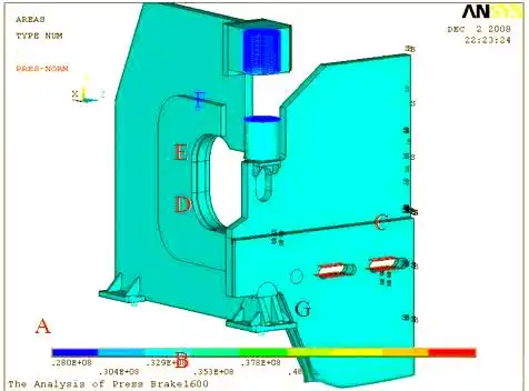
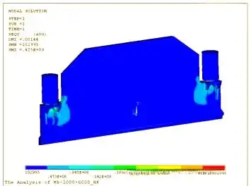
4.1 Stress and Deformation Findings
- Stress Concentrations: Initial analysis reveals high stress near direct load points, such as hydraulic cylinder connections, while most of the frame exhibits significant strength reserves.
- Stiffness Performance: The press brake frame demonstrates excellent stiffness, providing ample opportunity for material optimization without compromising structural integrity.
4.2 Optimization Strategies
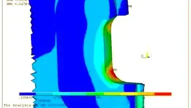
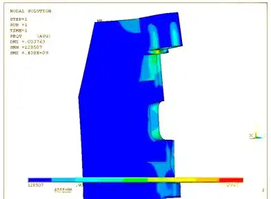
- Thickness Reduction: Non-critical plates are thinned to reduce material usage, lowering production costs.
- Reinforcement of Key Areas: Load-bearing regions, such as the throat and key connections, are strengthened to mitigate stress concentrations.
- Safety Validation: Post-optimization, finite element calculations confirm that the design meets safety standards. Stress cloud diagrams for the optimized frame and slider.
4.3 Optimization Benefits
- Improved Stress Distribution: The optimized frame achieves uniform stress distribution, reducing the risk of localized failure.
- Material Savings: Thinner plates in non-critical areas reduce material costs while maintaining performance.
- Enhanced Safety: Rigorous safety checks ensure the optimized design withstands operational loads, addressing user concerns about reliability.
5. Practical Applications and Industry Impact
The optimized press brake design offers significant benefits for manufacturers and end-users:
- Cost Efficiency: Reduced material usage lowers production costs, making CNC press brakes more competitive.
- Performance Enhancement: Uniform stress distribution and reinforced key areas improve durability and operational reliability.
- Scalability: The FEA methodology is adaptable to various press brake models, supporting innovation across the industry.
Conclusion
Finite element analysis and structural optimization of press brake frames enable manufacturers to achieve superior performance and cost efficiency. By simplifying models, employing advanced meshing, accurately defining constraints and loads, and optimizing critical components, this approach ensures that hydraulic press brakes meet rigorous safety and performance standards. Engineers and manufacturers can leverage these techniques to design robust, cost-effective CNC press brakes that meet modern industry demands.

Metalworking specialist with 12 years of experience in sheet metal fabrication and press brake applications, certified by ASME.