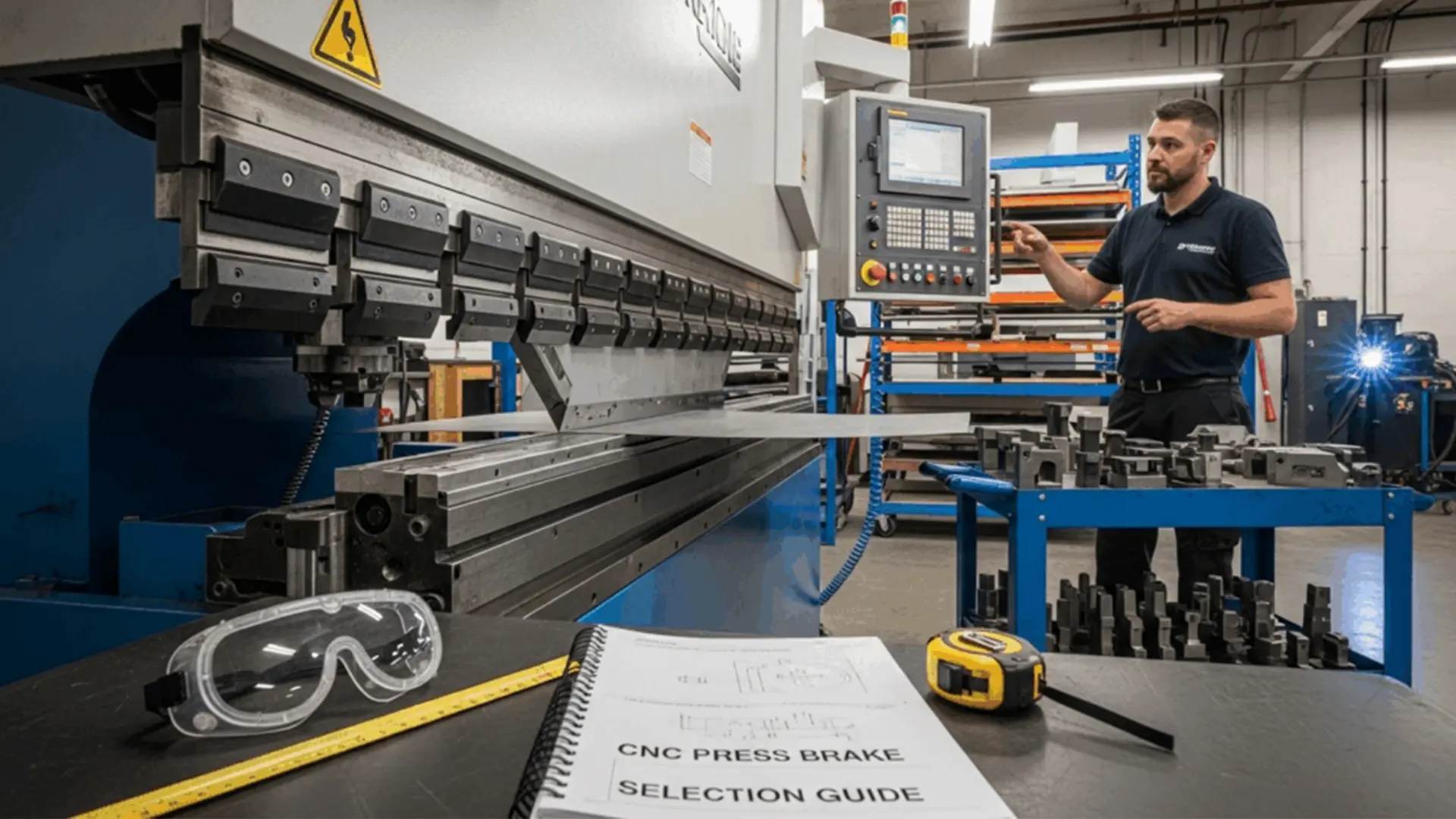
Common CNC Press Brake Faults and Solutions
CNC press brakes are critical for precision metal forming, but like any complex machinery, they can encounter faults that disrupt production. This guide provides a comprehensive overview of common mechanical, hydraulic, and electrical issues in CNC press brakes, along with practical solutions to restore functionality. Whether you’re a technician or an operator, understanding these faults and their fixes will enhance equipment reliability and efficiency.

1. Mechanical Faults and Solutions of Press Brake
Mechanical issues often arise from wear and tear or improper adjustments. Below are the most frequent mechanical faults in CNC press brakes and their solutions.
Fault 1: Excessive Clearance Between Slider and Guide Rail, Causing Abnormal Noise
ymptoms: The press brake emits unusual sounds during operation, indicating excessive play between the slider and guide rail.
Cause: Prolonged use leads to guide rail wear, increasing the clearance beyond acceptable limits.
Solution:
Inspect Wear: Check the guide rail pressure plate for signs of wear using precision measuring tools.
Replace Components: If wear is significant, replace the guide rail pressure plate with a new one compatible with your press brake model.
Adjust Clearance: Realign the guide rail to meet manufacturer-specified clearance tolerances, typically using shims or adjustment screws.
Preventive Maintenance: Regularly lubricate guide rails and schedule periodic inspections to prevent excessive wear.
Fault 2: Rear Gauge Transmission Failure
Symptoms: The rear gauge fails to move or moves erratically, affecting material positioning accuracy.
Cause: Disengagement of the key bar between the transmission shaft and synchronous pulley, or slippage of the synchronous belt.
Solution:
Reassemble Components: Disassemble the transmission system, realign the key bar, and secure the synchronous belt. Ensure proper tension in the belt to prevent future slippage.
Electrical Check: Inspect the motor and control circuits for faults, as electrical issues can mimic mechanical failure. Use a multimeter to verify continuity.
Preventive Tip: Regularly inspect the transmission system for wear and ensure proper alignment during maintenance checks.
Fault 3: Excessive Parallelism Deviation Between Rear Gauge Beam Linear Guide and Mold Centerline
Symptoms: Misaligned bends due to poor parallelism between the rear gauge beam and mold centerline.
Cause: Parallelism deviation exceeds the acceptable tolerance, often due to mechanical drift or improper setup.
Solution:
Loosen Synchronous Belt: Release the “X” axis synchronous belt to allow adjustments.
Realign Guide: Use a dial indicator to measure and adjust the linear guide to within the parallelism tolerance (typically ±0.1 mm).
Reinstall Belt: Securely reinstall the synchronous belt, ensuring proper tension.
Preventive Tip: Calibrate the rear gauge alignment during setup and after major maintenance to maintain accuracy.
Fault 4: Loose Connection Between Cylinder and Slider
Symptoms: Inaccurate bending angles or failure to locate the reference point, leading to inconsistent results.
Cause: Loose bolts or nuts connecting the cylinder to the slider.
Solution:
Inspect Connections: Check all bolts and nuts for looseness using a torque wrench.
Retighten: Tighten to the manufacturer’s specified torque values to ensure a secure connection.
Verify Alignment: Confirm that the cylinder and slider are properly aligned after tightening.
Preventive Maintenance: Include connection checks in routine maintenance schedules to avoid recurrence.
2. Hydraulic Faults and Solutions of Press Brake
Hydraulic system issues can significantly impact press brake performance. Below are common hydraulic faults and their resolutions.
Fault 1: No Pressure in the Hydraulic System
Symptoms: The press brake fails to generate sufficient force for bending.
Cause:
Proportional relief valve solenoid coil not energized or receiving incorrect voltage.
Stuck cartridge valve, main valve core, or blocked damping hole due to contamination.
Incorrect three-phase power phasing, causing motor reversal.
Solution:
Electrical Check: Use a multimeter to verify solenoid coil energization and voltage. Troubleshoot wiring or control system issues if necessary.
Clean Valves: Disassemble the relief valve, clean it with a suitable solvent, and remove debris from the damping hole. Reinstall carefully.
Correct Power Phasing: Check the three-phase power supply and correct phasing to ensure proper motor rotation.
Preventive Tip: Regularly filter hydraulic oil and inspect electrical connections to prevent valve and motor issues.
Fault 2: Slider Transitions from Fast to Slow with Excessive Delay
Symptoms: The slider pauses too long when switching from fast to slow speed, reducing efficiency.
Cause:
Low oil level, leaving the filling port exposed and causing insufficient filling.
Excessive fast-forward speed, leading to inadequate filling.
Contaminated oil causing the filling valve core to stick.
Solution:
Check Oil Level: Ensure the oil level is 5mm above the filling port to fully submerge it. Top up with manufacturer-recommended hydraulic oil if needed.
Adjust Speed: Modify system parameters to reduce fast-forward speed, allowing adequate filling time.
Clean Filling Valve: Disassemble and clean the filling valve to restore smooth valve core movement.
Preventive Maintenance: Monitor oil levels and quality regularly, replacing or filtering oil as needed.
Fault 3: Normal Slider Return and Fast-Forward, but Weak Manual Slow Descent
Symptoms: The slider operates normally in return and fast-forward modes but lacks power during manual slow descent.
Cause:
Malfunctioning “two-position four-way” valve, causing the filling valve to remain open.
Stuck filling valve due to contamination.
Solution:
Inspect Valve Operation: Check if the directional valve is energized or stuck. Repair electrical faults or free the valve core.
Clean Filling Valve: Disassemble, clean, and lubricate the filling valve to ensure smooth operation.
Preventive Tip: Use high-quality hydraulic oil and install filters to minimize contamination risks.
Fault 4: Slow Slider Return Speed with High Return Pressure
Symptoms: The slider returns slowly, and return pressure is unusually high.
Cause: Filling valve not fully opened, restricting oil flow.
Solution:
Refer to Fault 3’s solution: Clean the filling valve and check the directional valve for proper operation.
Additional Check: Verify hydraulic pump performance to rule out flow restrictions.
Preventive Tip: Schedule regular hydraulic system maintenance to prevent valve blockages.
3. Electrical System Faults and Solutions of Press Brake
Electrical faults can disrupt CNC press brake operation, often requiring precise diagnostics. Below are common issues and their fixes.
Fault 1: Low-Voltage Circuit Breaker Trips After Oil Pump Starts
Symptoms: The circuit breaker trips immediately after starting the oil pump.
Cause:
Phase loss in the power supply.
Severely clogged high-pressure filter, increasing motor current.
Low-voltage circuit breaker setting too low.
Solution:
Check Power Supply: Use a multimeter to confirm all phases are present. Correct wiring if phase loss is detected.
Inspect Filter: Replace the high-pressure filter if clogged, ensuring proper oil flow.
Adjust Breaker: Increase the circuit breaker setting to match the motor’s rated current, per manufacturer specifications.
Preventive Tip: Monitor power supply stability and replace filters regularly.
Fault 2: Failure to Locate Reference Point During Startup
Symptoms: The press brake cannot find the reference point, halting operation.
Cause:
Loose grating scale readhead connection, preventing alignment with the reference point.
Improper shutdown, leaving the slider away from the top dead center.
Solution:
Reconnect Grating Scale: Press the red stop button, secure the grating scale readhead, and manually lower the slider to align with the lower mold. Return to the reference point in semi-automatic or automatic mode.
Correct Shutdown Procedure: Manually lower the slider to align molds before shutdown, then restart and return to the reference point.
Preventive Tip: Train operators on proper shutdown procedures and routinely check grating scale connections.
Fault 3: System Screen Shows No Display, Appears Grayish-White, with Blinking Programming Key Indicator
Symptoms: The control system screen is blank or grayish, and the programming key blinks.
Cause: Overloaded program buffer memory due to uncleared programs.
Solution:
Initialize System: Disconnect the main power, press “+ +” and “- -” keys simultaneously, then power on to enter initialization mode.
Clear Memory: Input “1” to select the project, enter password “817,” and confirm to clear the buffer.
Preventive Tip: Clear unused programs after each job to prevent memory overload.
Fault 4: Inaccurate Grating Scale Counting, Causing Bending Angle Errors
Symptoms: Cumulative errors in “Y1” and “Y2” axis positioning lead to inaccurate bending angles.
Cause: Grating scale feedback signal drops pulses due to contamination or poor installation.
Solution:
Clean Grating Scale: Disassemble and clean the grating scale, ensuring dust and vibration protection.
Improve Installation: Redesign any improper mounting to enhance stability.
Repair or Replace: Return faulty grating scales to the manufacturer for repair or replacement.
Preventive Tip: Implement dust covers and vibration-dampening measures for grating scales.
Fault 5: “X” or “R” Axis Safety Distance Alarm After Programming
Symptoms: The system alarms and halts due to safety distance violations.
Cause: Conflict between mold safety distance settings, “X” or “R” axis limits, and programmed positions.
Solution:
Reprogram Parameters: Adjust the mold or program settings to eliminate conflicts.
Verify Limits: Check “X” and “R” axis limit settings in the control system.
Preventive Tip: Validate program parameters during setup to ensure compatibility with mold configurations.
Fault 6: “X” or “R” Axis Drive Motor Error Alarm
Symptoms: The system displays a motor error alarm (e.g., 16# for overload, 22# for encoder issues).
Cause:
16# Alarm: Motor overload due to excessive mechanical resistance.
22# Alarm: Encoder feedback signal issues from poor connections or interference.
Solution:
For 16# Alarm: Inspect “X” and “R” axis transmission for flexibility, addressing excessive resistance or mechanical limits.
For 22# Alarm: Check encoder connections for loose contacts, disconnection, or signal interference.
Preventive Tip: Regularly lubricate transmission components and shield encoder cables from electromagnetic interference.
Fault 7: Discrepancy Between “Y1” and “Y2” Axis Displayed and Actual Positions
Symptoms: The control system shows incorrect “Y1” and “Y2” axis positions.
Cause: Inaccurate reference point calibration.
Solution:
Reinitialize Reference Point: Recalibrate the “Y1” and “Y2” axes to align with the actual positions.
Preventive Tip: Perform reference point calibration after major adjustments or power interruptions.
Fault 8: Discrepancy Between System’s “X” or “R” Axis Displayed and Actual Positions
Symptoms: The displayed “X” or “R” axis positions do not match their actual positions.
Cause: Axis positions were moved during power-off, while the system retained the pre-shutdown position.
Solution:
Reinitialize Axes: Recalibrate the “X” and “R” axis positions in the control system.
Preventive Tip: Ensure axes are not manually moved during power-off states.
Fault 9: “Y1” and “Y2” Axis Position Deviation Exceeds Allowable Synchronization Range
Symptoms: The slider cannot move due to excessive deviation between “Y1” and “Y2” axes.
Cause: Improper shutdown without aligning the slider with molds, causing deviation from tool drop.
Solution:
Adjust Parameters: Increase the synchronization deviation range by Ascending 5mm in system parameters.
Manual Correction: Enter manual mode, lower the slider, and allow the system to auto-correct the position.
Preventive Tip: Always align the slider with molds before shutdown to prevent deviation.
Conclusion
Maintaining a CNC press brake requires proactive troubleshooting and regular maintenance. By addressing mechanical, hydraulic, and electrical faults promptly using the solutions outlined above, you can minimize downtime and ensure consistent bending accuracy. Implement a routine maintenance schedule, train operators on proper procedures, and use high-quality components to extend the lifespan of your press brake.
For more information on CNC press brake maintenance or advanced troubleshooting, contact your equipment supplier or refer to the manufacturer’s manual.

Metalworking specialist with 12 years of experience in sheet metal fabrication and press brake applications, certified by ASME.