How to Properly Use Press Brake Crowning
Press brake crowning is a critical technique that involves adjusting the physical position of the upper or lower tooling to counteract material springback and machine deflection. This ensures precise bends across the entire workpiece length. Studies indicate that up to 90% of bending errors stem from springback, while effective crowning can reduce these inaccuracies by over 70%. Crowning methods fall into two primary categories:
Deflection Crowning: Ideal for long workpieces (over 2 meters), this addresses sagging in the middle by using hydraulic cylinders or wedges to lift the lower table. Typical crowning ranges from 0.05-0.3 mm per meter.
Angle Crowning: This fine-tunes the punch penetration depth to offset springback. For instance, with 6mm-thick Q235 steel, springback might be around 3°, requiring an additional 1.2mm stroke adjustment.
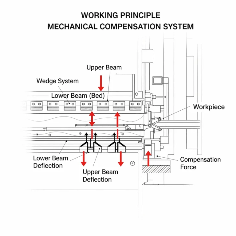
Why Does a Press Brake Need a Crowning Device?
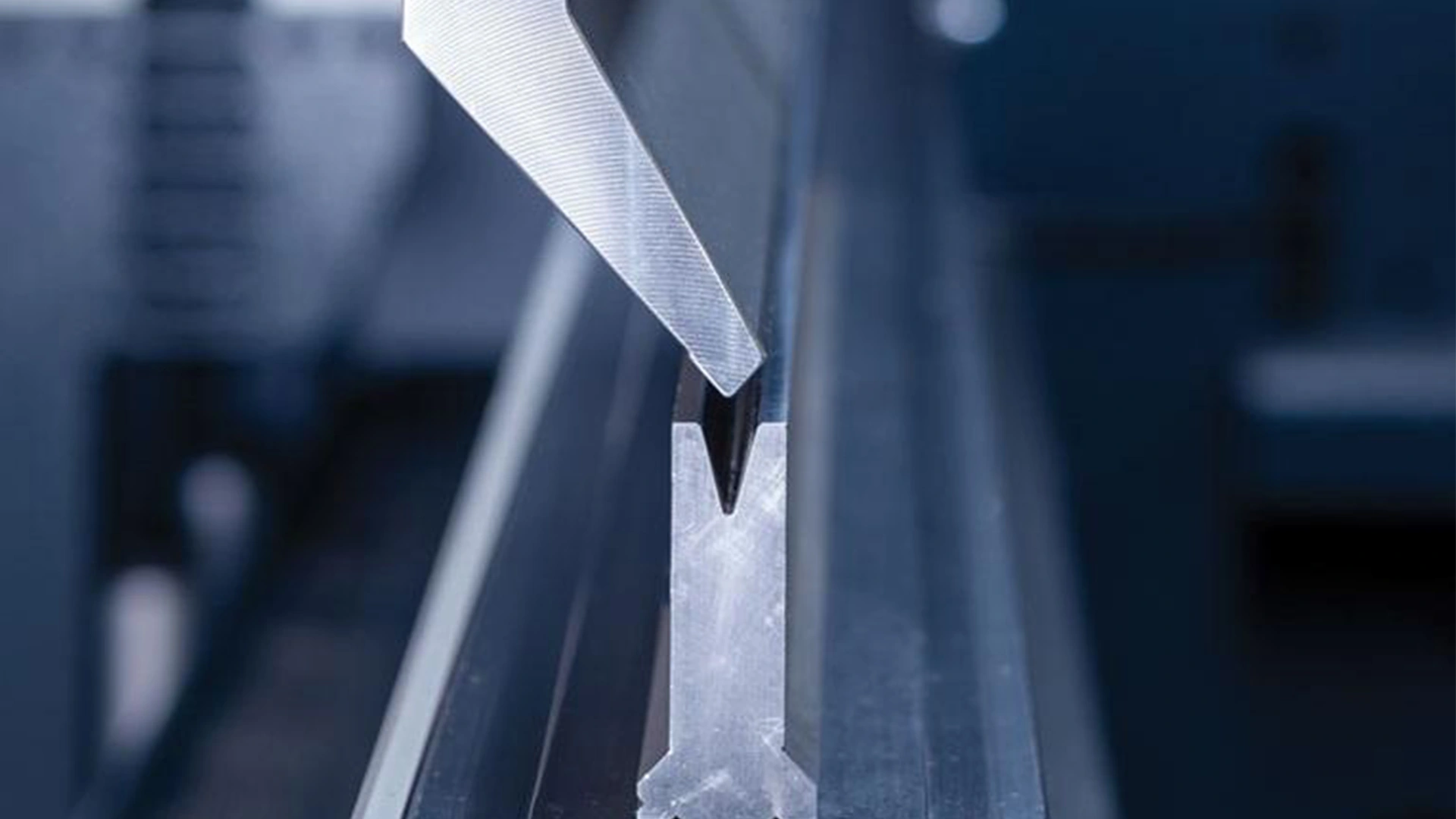
During bending operations, the ram and bed of a press brake deform under tonnage, leading to inconsistent punch penetration along the workpiece. This unevenness compromises part accuracy, often resulting in angular variations or poor straightness. To mitigate this, engineers have developed various crowning systems. Broadly, these include lower bed crowning, where the table is curved upward in a symmetrical arch, and upper ram crowning, which creates a downward curve on the punch or slider. Both approaches minimize angular errors effectively, though their impact on part straightness differs. Modern systems, such as hydraulic or wedge-based mechanisms, allow for real-time adjustments to maintain uniform bends.
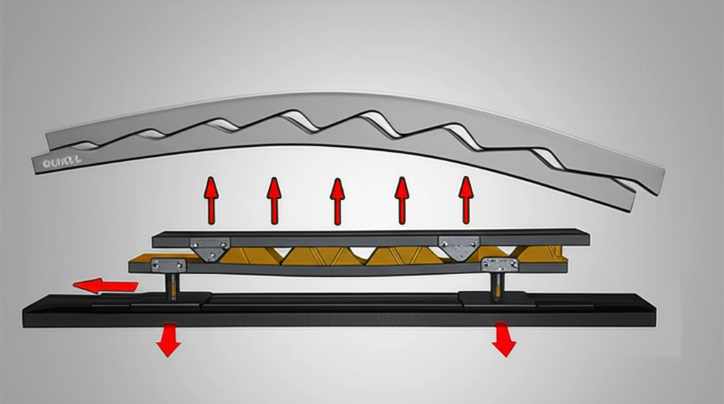
Natural Deflection of Bent Parts
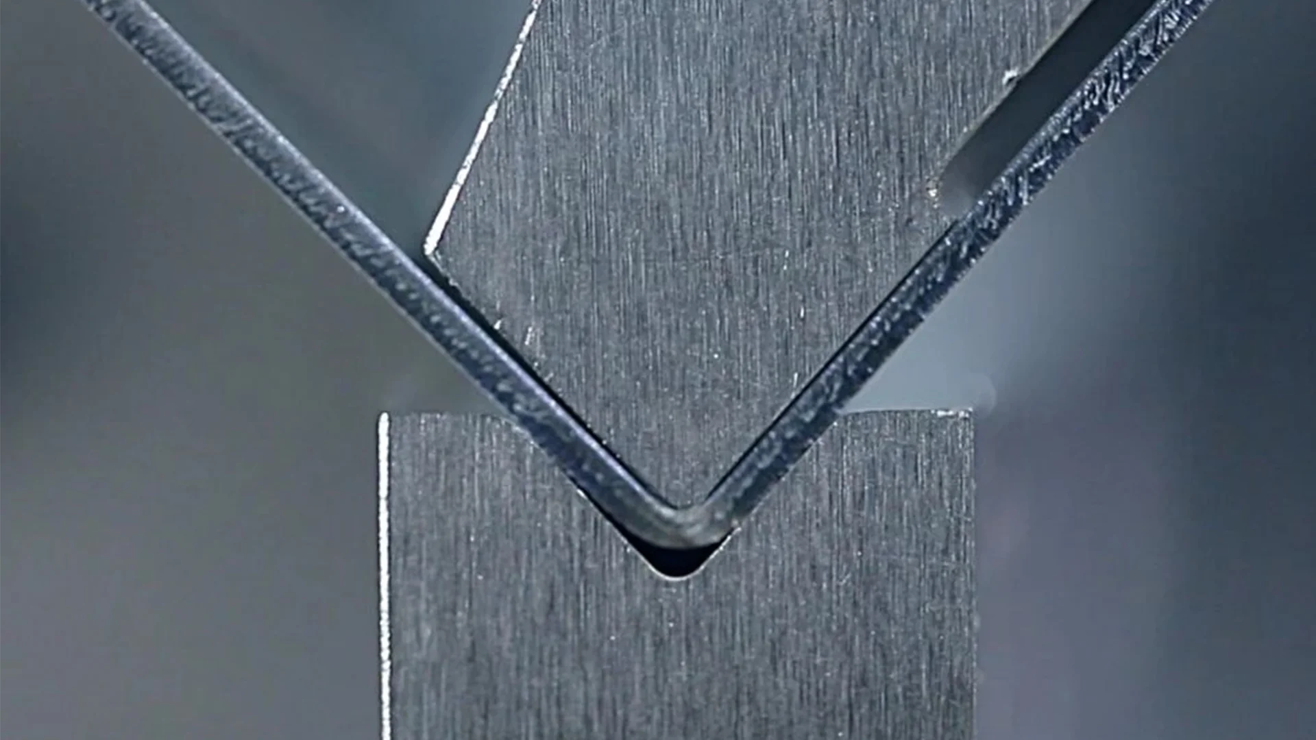
After bending, workpieces exhibit natural deflection along their edges, quantified by maximum sag. In the bending zone, the metal undergoes plastic deformation: compressive stresses on the inner arc and tensile on the outer, creating a longitudinal moment around the axis. This moment keeps the part aligned with the die during force application. Upon ram retraction, the forces release, causing elastic recovery that bends the part oppositely—resulting in natural crowning. For clarity, visualize the deformation zone flattened: the upper layer compresses longitudinally, while the lower stretches, amplifying post-bend curvature without crowning.
Impact of Two Different Press Brake Crowning Methods on Part Straightness
Lower bed crowning produces an upward-curving crowning profile, while upper ram crowning yields a downward bend. The natural deflection curve of bent parts typically arches upward. Crowning amounts are calibrated to match machine deflection, which is relatively small. However, unloading reduces this induced crowning slightly, often making it less than the part’s inherent deflection. Consequently, lower bed methods may better preserve straightness for certain materials, whereas upper methods excel in angle precision but require careful tuning to avoid overcompensation.
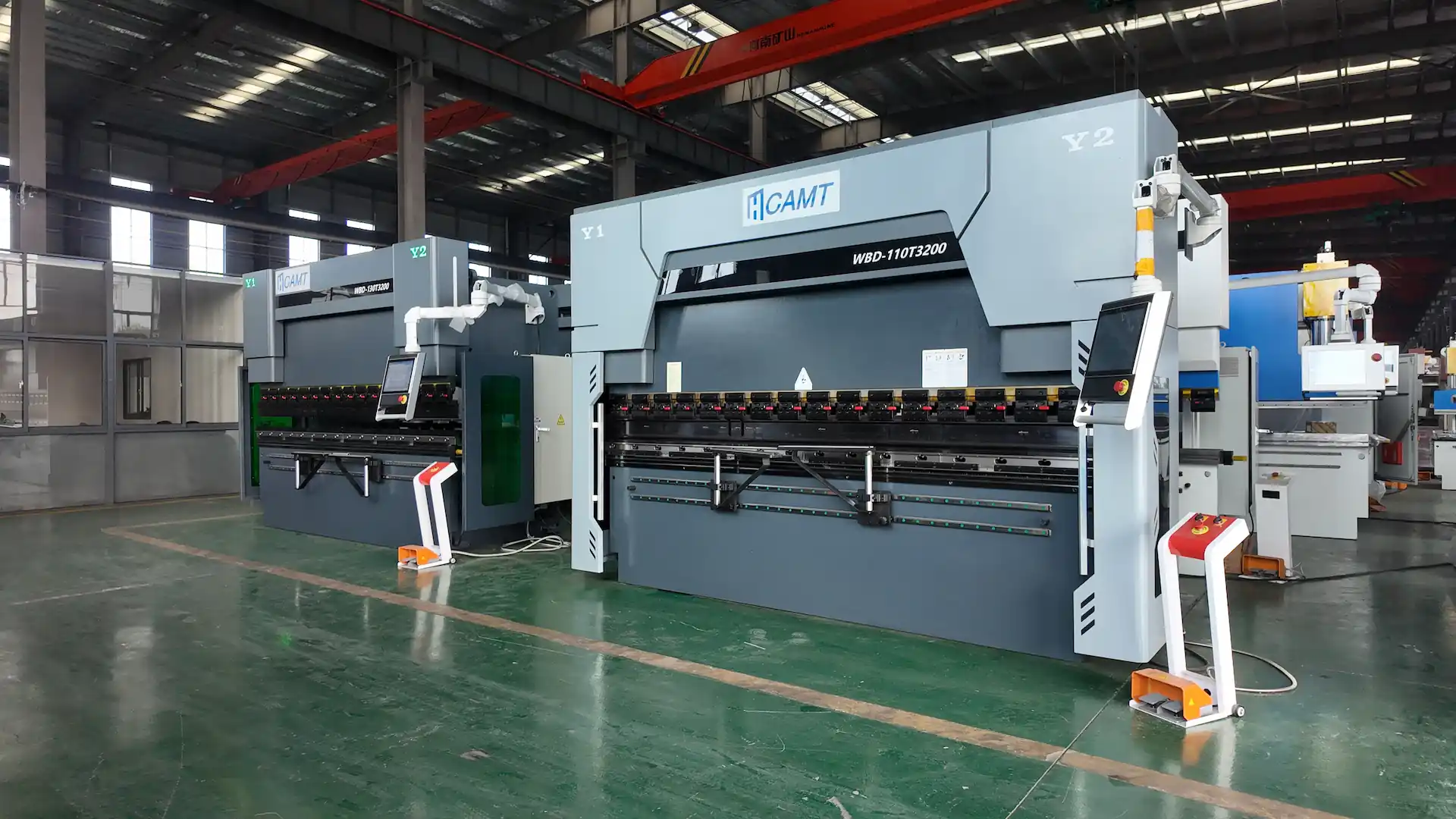
Operation Steps and Parameter Settings (Example: CAMT 80T Model)
Follow these steps for optimal crowning setup:
Calibrate the Reference Surface:
Clean the table and tooling, then level using a 0.02 mm/m precision instrument.
Run three full-stroke cycles unloaded to clear mechanical play.
Input Crowning Values: Use material-specific guidelines:
Material Thickness (mm) | Crowning Factor (mm/100mm) | Max Crowning (mm) |
1-3 | 0.08-0.15 | 1.2 |
4-6 | 0.15-0.25 | 2.5 |
8-12 | 0.3-0.5 | 4.0 |
Trial Bend Verification:
Measure the first part’s angle post-bend. If deviation exceeds 0.5°, apply correction: Crowning Value = Measured Deviation × 0.7 (empirical rule).
Common Problems and Solutions of Press Brake Crowning
Over/Under Crowning:
Symptoms: Angles greater than 90° (under) or less (over).
Fix: Each 0.1mm adjustment influences about 1°; iterate in small increments.
Unusual Noises or Vibrations:
Inspect tooling clamp force (minimum 50kN per TRUMPF specs) to prevent shifts during crowning.
Press Brake Crowning Maintenance and Safety Points
Weekly: Lubricate crowning components with ISO VG68 hydraulic oil.
Safety: Never exceed 120% of rated crowning to avoid guide rail distortion. Precise crowning can achieve repeatability within ±0.1° (per JIS B 6542), boosting yield rates. Always adapt parameters for material properties—e.g., stainless steel springs back 20% more than carbon steel.
Summary
Mastering press brake crowning ensures consistent, high-precision bends by countering deflection and springback. By selecting the right system and following calibrated procedures, operators can minimize errors and enhance productivity. Embrace dynamic adjustments tailored to your setup for optimal results in sheet metal fabrication.

Metalworking specialist with 12 years of experience in sheet metal fabrication and press brake applications, certified by ASME.