CAMT
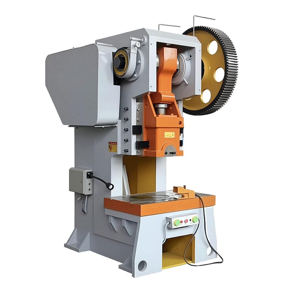
J21 Fixed Bench Punching Machine

CAMT
J21 Fixed Bench Punching Machine
CAMT punching machine is a highly efficient industrial equipment that utilizes mechanical power to apply force through dies, performing processes such as punching, forming, bending, and drawing on metallic or non-metallic materials. Its core operating principles are categorized into mechanical (crank-slider mechanism) and hydraulic (Pascal’s principle), with the former suited for high-speed mass production (e.g., electronic component stamping) and the latter excelling in low-speed, high-precision forming (e.g., automotive sheet metal deep drawing).
A standard press consists of a frame (C-type open-back or straight-side), drive system (mechanical crankshaft/hydraulic cylinder), and intelligent control system (PLC), achieving precision up to ±0.01mm and speeds as high as 120 strokes per minute.
Renowned for its efficiency (0.1-second cycle time), energy savings (flywheel energy storage reduces consumption by 40%), and flexible production (quick die change), press machines are indispensable in modern manufacturing, widely used in automotive (door hinges), precision electronics (mobile phone frames), and new energy sectors (battery casings).
Add Your Tooltip Text Here
Add Your Tooltip Text Here
Robust & Simple Design
High Productivity
Operational Flexibility
Cost-Effective
CAMT Mechanical Punching Stamping
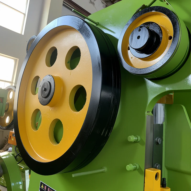
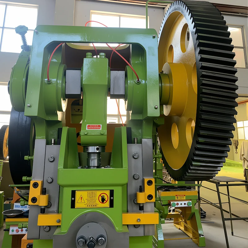
Crank-slider mechanism for power transmission
- Motor drives the flywheel via a belt pulley, storing kinetic energy. The clutch engages to transfer motion to the crankshaft.
- Crankshaft converts rotary motion into linear reciprocating motion of the connecting rod, which moves the slide (upper die) vertically.
- Slide descends to close the upper and lower dies for punching, bending, or forming; it resets via a brake and return springs during ascent.
- Flywheel’s inertia balances load fluctuations, ensuring smooth operation.
CAMT Components of Punching Machine
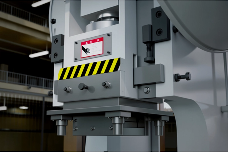
Key Mechanical Structural Configuration
- C-type open-front design for high rigidity and easy die/material access.
- Crankshaft, connecting rod, and slide form the main drive chain, with precision directly affecting stamping quality.
- Clutch controls slide movement.
- Foot pedal or push-button operation, with optional photoelectric safety guards.
- Die shank clamp, knock-out mechanism (ejection), and lubrication
Stamping Application for Punching Machine
Widely used in the following industries
- Blanking: Sheet metal cutting/punching (e.g., electrical enclosures, hardware).
- Forming: Bending/shallow drawing (e.g., brackets, hinges).
- Press-Fitting: Bearing/bushing assembly.
- Rubber Industry: Vulcanization and compression molding.
| Name | J23-10 | J23-16 | J23-25 | J23-40 | J23-63 | J23-80 | J21-100 | J21-125 | J21-160 | JH21-200 | JH21-250 |
|---|---|---|---|---|---|---|---|---|---|---|---|
| Nominal force KN | 100 | 160 | 250 | 400 | 630 | 800 | 1000 | 1250 | 1600 | 2000 | 2500 |
| Stroke of Nominal force mm | 2 | 2 | 3 | 5 | 5 | 6 | 6 | 8 | 8 | 12 | 14 |
| Stroke of sliding block mm | 50 | 60 | 70 | 100 | 100 | 120 | 130 | 130 | 160 | 180 | 200 |
| Number of strokes times/min | 130 | 110 | 60 | 55 | 50 | 45 | 43 | 35 | 28 | 28 | 28 |
| Closed height mm | 180 | 190 | 210 | 325 | 350 | 370 | 380 | 400 | 400 | 420 | 430 |
| Closed height adjustment mm | 35 | 40 | 50 | 65 | 80 | 90 | 100 | 110 | 120 | 120 | 130 |
| Distance from slider block centre to the frame mm | 130 | 150 | 180 | 250 | 260 | 275 | 310 | 340 | 390 | 390 | 390 |
| Length between columns mm | 140 | 160 | 230 | 270 | 310 | 410 | 520 | 560 | 580 | 680 | 700 |
| Hole size for die handle Diameter mm | 35 | 35 | 40 | 50 | 50 | 60 | 60 | 70 | 80 | 90 | 100 |
| Depth mm | 50 | 60 | 60 | 70 | 70 | 70 | 90 | 120 | 150 | 150 | 170 |
| Size of worktable Left-right mm | 360 | 440 | 500 | 680 | 720 | 750 | 900 | 930 | 1140 | 1390 | 1500 |
| Front-back mm | 240 | 270 | 320 | 460 | 480 | 530 | 630 | 630 | 740 | 820 | 900 |
| Blanking hole diameter mm | 80 | 100 | 130 | 150 | 160 | 180 | 180 | 200 | 200 | 220 | 250 |
| Table plate thickness mm | 35 | 40 | 50 | 65 | 80 | 100 | 120 | 130 | 150 | 150 | 150 |
| The maximum tilt angle • | 35 | 35 | 30 | 30 | 20 | 20 | |||||
| Dimensions Left-right mm | 680 | 730 | 920 | 1060 | 1130 | 1350 | 1480 | 1590 | 1855 | 2015 | 2340 |
| Front-back mm | 630 | 950 | 1180 | 1435 | 1480 | 1715 | 1815 | 1890 | 2045 | 2475 | 2675 |
| Height mm | 1658 | 1750 | 2040 | 2350 | 2450 | 2670 | 2750 | 2850 | 2920 | 3780 | 3850 |
| Power KW | 1.1 | 1.5 | 2.2 | 4 | 5.5 | 7.5 | 11 | 11 | 15 | 18.5 | 22 |
Advantage:
- Mechanical drive ensures low failure rates and maintenance costs vs. hydraulic presses.
- Fast cycling (up to 120 SPM) for mass production.
- Open-frame allows manual/semi-automatic feeding (compatible with feeders).
- Lower upfront cost and energy consumption (flywheel reduces peak motor load).