Why Needs Press Brake Crowning
Press Brake Frame deflection continues to be one of the most persistent sources of quality variation in modern sheet metal bending. Even small amounts of center bow — typically 0.4–1.5 mm on 3-meter machines — can produce angle deviations of ±0.8° to ±2.2°, depending on material thickness, tensile strength and bend length. This guide provides a current (2026) overview of crowning technologies used in CNC press brakes, including:- Physics and calculation of deflection
- Comparison of mechanical, hydraulic and dynamic (real-time) crowning systems
- Selection criteria and typical ROI periods
- Implementation steps, programming guidelines and calibration protocols
- Maintenance recommendations and common performance issues
1. Understanding Press Brake Frame Deflection
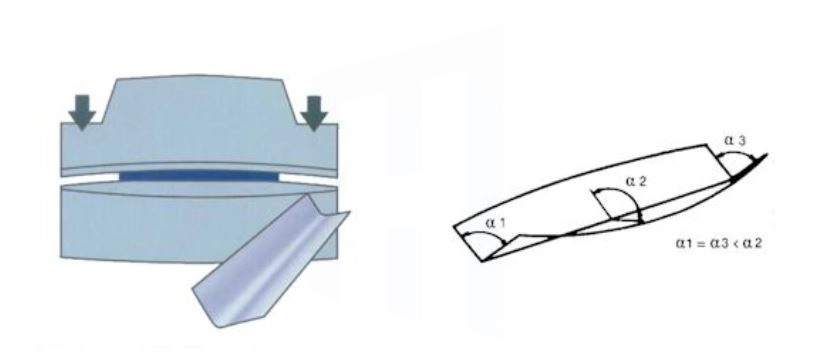
When bending force is applied, the upper ram and lower bed experience elastic deformation in a roughly parabolic pattern. Maximum deflection occurs near the center of the working length because the side frames resist movement at the ends. Simplified deflection formula (Euler–Bernoulli beam theory approximation):δ_max ≈ (F × L³) / (48 × E × I)
- δ_max = center deflection (mm)
- F = total bending force (kN)
- L = distance between side frames (m)
- E = modulus of elasticity of frame material (≈ 210 GPa for cast steel / welded frames)
- I = second moment of area of the beam cross-section (m⁴)
Example: typical 100–320 ton, 3-meter press brake
3 mm stainless steel 304, V = 24 mm, required force ≈ 220–260 tons
→ estimated center deflection 0.55–0.85 mm without compensation
→ resulting angle variation ≈ 90.9°–92.1° (center) vs 89.4°–90.1° (ends).
2. 2026 Crowning System Types – Technical Comparison
| Type | Adjustment Method | Typical Accuracy | Setup Time | Initial Cost Range (USD) | Best Suited For | Average ROI Period |
|---|---|---|---|---|---|---|
| Mechanical (wedge / shim) | Manual wedge position or shim stack | ±0.4° – ±0.8° | 10–25 min | 4,000 – 9,500 | High-volume production of similar parts | 12–18 months |
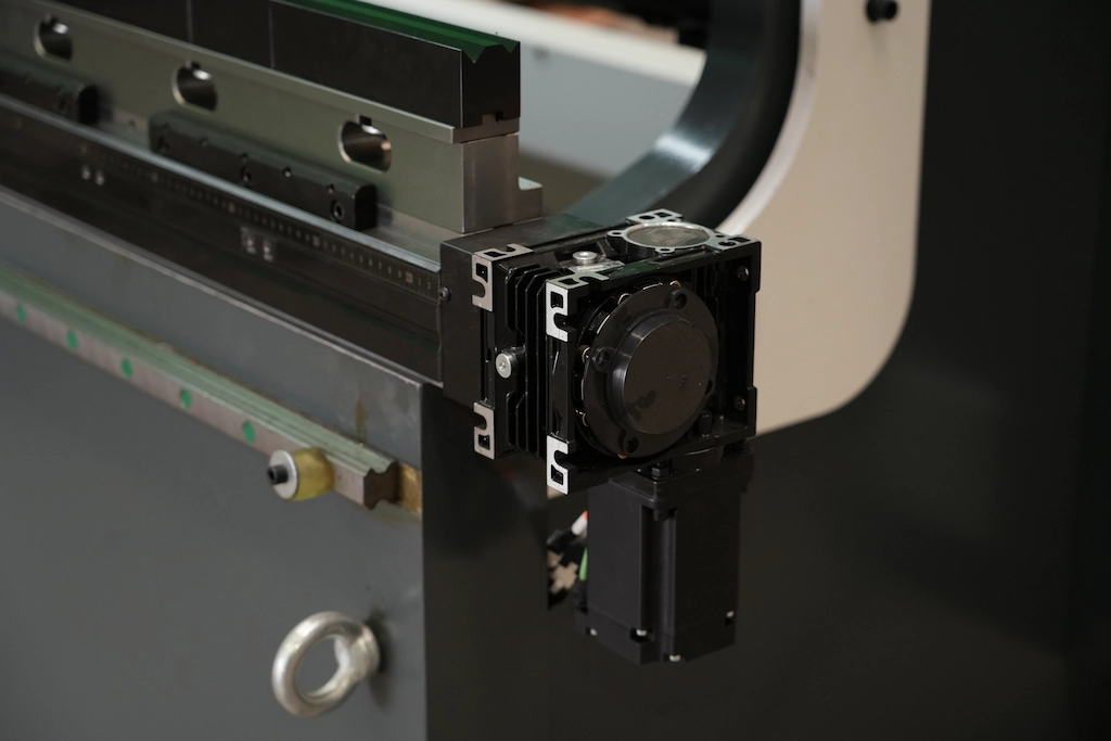
| Hydraulic (cylinder-based) | Proportional hydraulic cylinders | ±0.15° – ±0.4° | 1–6 min | 11,000 – 24,000 | Job shops with 20–120 daily setups | 6–11 months |
| Dynamic / Adaptive CNC | Real-time sensor feedback + CNC interpolation | ±0.05° – ±0.15° | <90 sec | 22,000 – 42,000 | High-mix, tight tolerance, Industry 4.0 | 4–8 months |
3. Most Common Sources of Crowning-Related Quality Issues (2026)
- Using fixed mechanical crowning for >12 different material / thickness combinations per shift
- Compensation tables not updated after punch / die change (V-opening change of 2–4 mm can shift required crowning by 30–60%)
- Insufficient compensation for springback differences: austenitic stainless typically requires 20–35% more crowning stroke than mild steel
- Hydraulic pressure instability caused by air in lines, worn seals or contaminated fluid
- Lack of monthly verification bends → gradual accuracy drift of 0.3–0.8° over 4–8 months
4. Practical Implementation Steps (2026 Standard Procedure)
- Baseline deflection measurement Perform test bends on representative materials… Record angle at 300–500 mm intervals.
- Create material-specific compensation library Typical starting values (3-meter machine): • Mild steel 2–4 mm → 1.8–3.2 mm crowning • 304/316 SS 2–4 mm → 2.6–4.5 mm • Hardox 450 6–10 mm → 5.5–9.0 mm
- Enable dynamic / adaptive mode (if available)
- Validation & fine-tuning Bend 3–5 test pieces → adjust until variation ≤ ±0.12°(Detailed step-by-step guide on trial bends, angle measurement corrections, and avoiding over/under crowning)
- Activate in-process monitoring (if supported)
5. Recommended Maintenance & Calibration Schedule
| Task | Frequency | Purpose / Expected Outcome |
|---|---|---|
| Visual inspection of cylinders & lines | Weekly | Detect leaks, contamination, damage |
| Bleed air from hydraulic system | Weekly–Bi-weekly | Eliminate pressure fluctuation (0.2–0.6° drift) |
| Full calibration test bends | Monthly | Verify accuracy remains within ±0.15° |
| Sensor zero / gain recalibration | Quarterly | Maintain dynamic system precision |
| Complete system service (seals, filters, oil) | Annually | Extend service life 4–7 years |
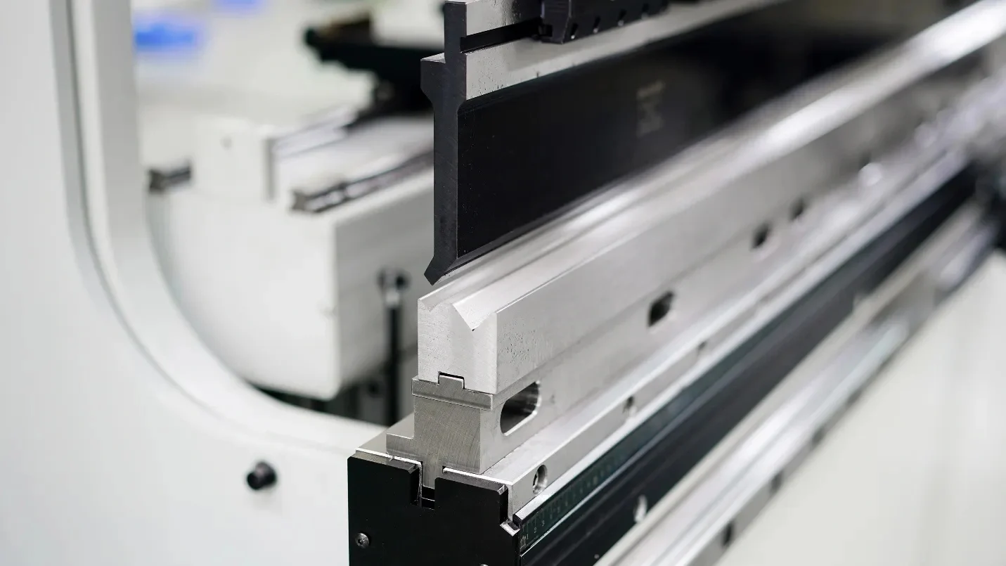
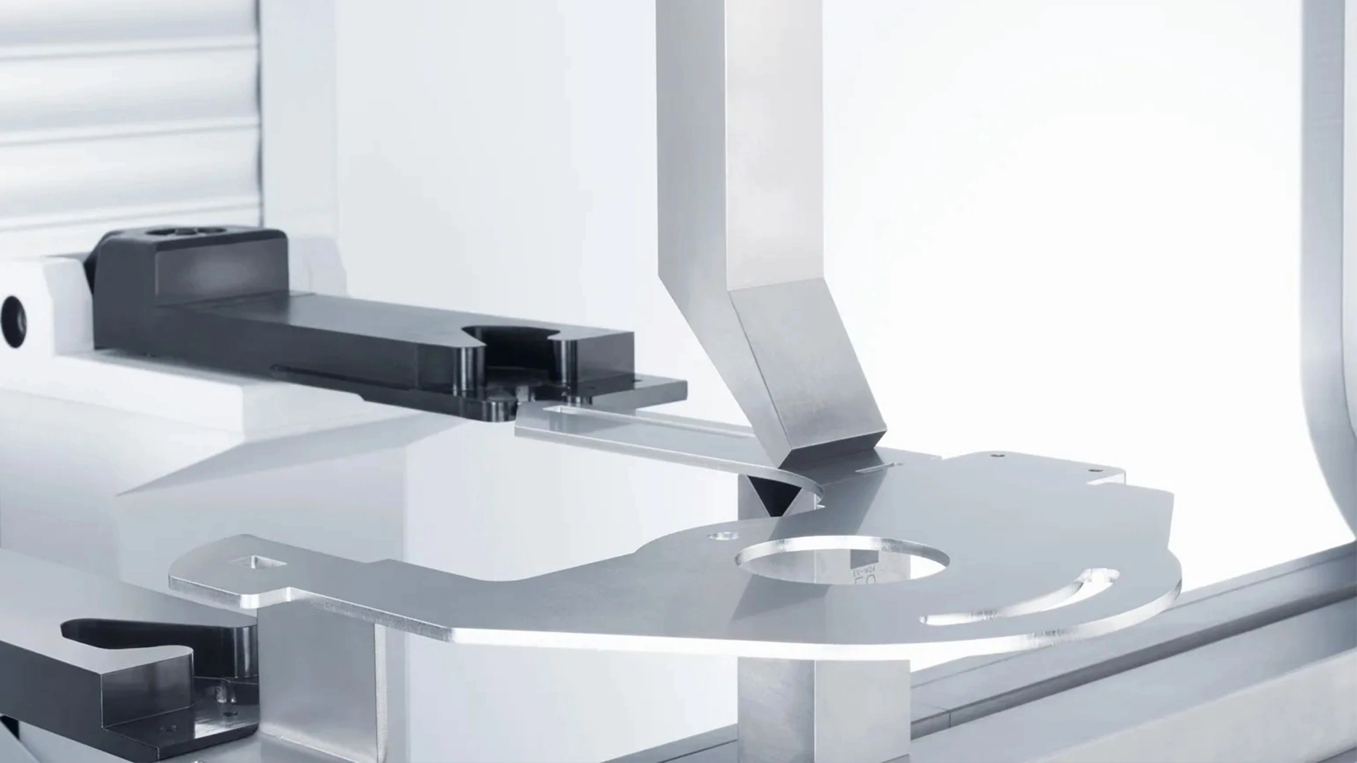
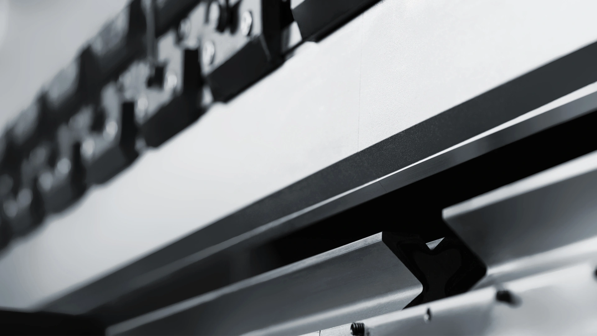
Understanding press brake deflection compensation types and proper usage for accuracy.

6. Summary – Choosing the Right Crowning Solution in 2026
- High-volume, low-mix production → mechanical crowning remains cost-effective
- Medium to high mix job shops → hydraulic crowning offers best balance
- High-value parts, tight tolerances, advanced alloys → dynamic real-time adaptive crowning delivers the lowest scrap rate and fastest payback
Conclusion: Deflection compensation is no longer optional for competitive fabrication shops. Accurate crowning directly impacts first-pass yield, rework hours, material waste and customer satisfaction.
For machine-specific recommendations or current compensation table templates suitable for Delem, Cybelec or ESA controls, refer to manufacturer documentation or consult your press brake supplier.