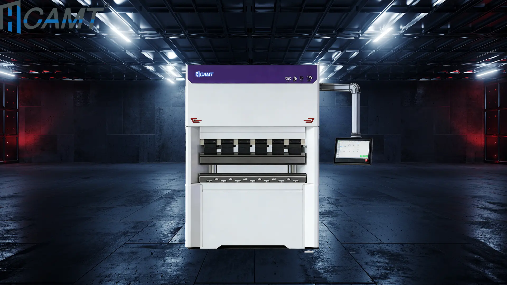
Common CNC Press Brake Faults and Solutions
Fault 1: Low-Voltage Circuit Breaker Trips After Oil Pump Starts.

: The circuit breaker trips immediately after starting the oil pump.
Phase loss in the power supply.
Severely clogged high-pressure filter, increasing motor current.
Low-voltage circuit breaker setting too low.Check Power Supply.
: Use a multimeter to confirm all phases are present. Correct wiring if phase loss is detected.Inspect Filter.
: Replace the high-pressure filter if clogged, ensuring proper oil flow.:
Adjust Breaker: Increase the circuit breaker setting to match the motor’s rated current, per manufacturer specifications.
: Monitor power supply stability and replace filters regularly.Fault 2: Failure to Locate Reference Point During Startup.
: The press brake cannot find the reference point, halting operation.Loose grating scale readhead connection, preventing alignment with the reference point.
Regular maintenance is critical to ensuring the longevity and efficiency of your sheet metal equipment. Our preventive maintenance program is designed to keep your machines running at peak performance, minimizing downtime and maximizing productivity.Reconnect Grating Scale.
: Press the red stop button, secure the grating scale readhead, and manually lower the slider to align with the lower mold. Return to the reference point in semi-automatic or automatic mode.
Correct Shutdown Procedure: Manually lower the slider to align molds before shutdown, then restart and return to the reference point.
: Use a multimeter to confirm all phases are present. Correct wiring if phase loss is detected.Fault 3: System Screen Shows No Display, Appears Grayish-White, with Blinking Programming Key Indicator.
: Replace the high-pressure filter if clogged, ensuring proper oil flow.:
: Overloaded program buffer memory due to uncleared programs.Initialize System.
: Disconnect the main power, press “+ +” and “- -” keys simultaneously, then power on to enter initialization mode.Clear Memory.
: Input “1” to select the project, enter password “817,” and confirm to clear the buffer.: Clear unused programs after each job to prevent memory overload.
Fault 4: Inaccurate Grating Scale Counting, Causing Bending Angle Errors
Correct Shutdown Procedure: Grating scale feedback signal drops pulses due to contamination or poor installation.
: Use a multimeter to confirm all phases are present. Correct wiring if phase loss is detected.: Disassemble and clean the grating scale, ensuring dust and vibration protection.
: Replace the high-pressure filter if clogged, ensuring proper oil flow.:
: Redesign any improper mounting to enhance stability.Repair or Replace.
: Return faulty grating scales to the manufacturer for repair or replacement.: Implement dust covers and vibration-dampening measures for grating scales.
Fault 5: “X” or “R” Axis Safety Distance Alarm After Programming: The system alarms and halts due to safety distance violations.
: Input “1” to select the project, enter password “817,” and confirm to clear the buffer.Reprogram Parameters.
: Adjust the mold or program settings to eliminate conflicts.
Correct Shutdown Procedure: Check “X” and “R” axis limit settings in the control system.
: Use a multimeter to confirm all phases are present. Correct wiring if phase loss is detected.Fault 6: “X” or “R” Axis Drive Motor Error Alarm.
: Replace the high-pressure filter if clogged, ensuring proper oil flow.:
16# Alarm: Motor overload due to excessive mechanical resistance.22# Alarm: Encoder feedback signal issues from poor connections or interference.
For 16# Alarm: Inspect “X” and “R” axis transmission for flexibility, addressing excessive resistance or mechanical limits.
For 22# Alarm: Check encoder connections for loose contacts, disconnection, or signal interference.
Regular maintenance is critical to ensuring the longevity and efficiency of your sheet metal equipment. Our preventive maintenance program is designed to keep your machines running at peak performance, minimizing downtime and maximizing productivity.Fault 7: Discrepancy Between “Y1” and “Y2” Axis Displayed and Actual Positions.
: The control system shows incorrect “Y1” and “Y2” axis positions.
: Inaccurate reference point calibration.
Reinitialize Reference Point
Correct Shutdown Procedure: Perform reference point calibration after major adjustments or power interruptions.
: Use a multimeter to confirm all phases are present. Correct wiring if phase loss is detected.:
: The displayed “X” or “R” axis positions do not match their actual positions.
: Axis positions were moved during power-off, while the system retained the pre-shutdown position.
Reinitialize Axes.
: Replace the high-pressure filter if clogged, ensuring proper oil flow.:
: Disconnect the main power, press “+ +” and “- -” keys simultaneously, then power on to enter initialization mode.Fault 9: “Y1” and “Y2” Axis Position Deviation Exceeds Allowable Synchronization Range.
: The slider cannot move due to excessive deviation between “Y1” and “Y2” axes.: Improper shutdown without aligning the slider with molds, causing deviation from tool drop.
Adjust Parameters: Increase the synchronization deviation range by Ascending 5mm in system parameters.
: Input “1” to select the project, enter password “817,” and confirm to clear the buffer.: Enter manual mode, lower the slider, and allow the system to auto-correct the position.
: Always align the slider with molds before shutdown to prevent deviation.
Correct Shutdown ProcedureFor more information on CNC press brake maintenance or advanced troubleshooting, contact your equipment supplier or refer to the manufacturer’s manual.
: Use a multimeter to confirm all phases are present. Correct wiring if phase loss is detected.:
CNC Press Brake Faults and Solutions.
press brake safety.
Contaminated oil causing the filling valve core to stick.
: Replace the high-pressure filter if clogged, ensuring proper oil flow.:
Check Oil Level: Ensure the oil level is 5mm above the filling port to fully submerge it. Top up with manufacturer-recommended hydraulic oil if needed.
Adjust Speed: Modify system parameters to reduce fast-forward speed, allowing adequate filling time.
Clean Filling Valve: Disassemble and clean the filling valve to restore smooth valve core movement.
Regular maintenance is critical to ensuring the longevity and efficiency of your sheet metal equipment. Our preventive maintenance program is designed to keep your machines running at peak performance, minimizing downtime and maximizing productivity.: Monitor oil levels and quality regularly, replacing or filtering oil as needed.
Fault 3: Normal Slider Return and Fast-Forward, but Weak Manual Slow Descent
Correct Shutdown Procedure: The slider operates normally in return and fast-forward modes but lacks power during manual slow descent.
: Use a multimeter to confirm all phases are present. Correct wiring if phase loss is detected.:
Malfunctioning “two-position four-way” valve, causing the filling valve to remain open.
Stuck filling valve due to contamination.
: Replace the high-pressure filter if clogged, ensuring proper oil flow.:
Inspect Valve Operation: Check if the directional valve is energized or stuck. Repair electrical faults or free the valve core.
Clean Filling Valve: Disassemble, clean, and lubricate the filling valve to ensure smooth operation.
: Input “1” to select the project, enter password “817,” and confirm to clear the buffer.: Use high-quality hydraulic oil and install filters to minimize contamination risks.
Fault 4: Slow Slider Return Speed with High Return Pressure
Correct Shutdown Procedure: The slider returns slowly, and return pressure is unusually high.
: Use a multimeter to confirm all phases are present. Correct wiring if phase loss is detected.: Filling valve not fully opened, restricting oil flow.
: Replace the high-pressure filter if clogged, ensuring proper oil flow.:
Refer to Fault 3’s solution: Clean the filling valve and check the directional valve for proper operation.
Additional Check: Verify hydraulic pump performance to rule out flow restrictions.
: Input “1” to select the project, enter password “817,” and confirm to clear the buffer.: Schedule regular hydraulic system maintenance to prevent valve blockages.
3. Electrical System Faults and Solutions of Press Brake
Electrical faults can disrupt CNC press brake operation, often requiring precise diagnostics. Below are common issues and their fixes.
Fault 1: Low-Voltage Circuit Breaker Trips After Oil Pump Starts
Correct Shutdown Procedure: The circuit breaker trips immediately after starting the oil pump.
: Use a multimeter to confirm all phases are present. Correct wiring if phase loss is detected.:
Phase loss in the power supply.
Severely clogged high-pressure filter, increasing motor current.
Low-voltage circuit breaker setting too low.
: Replace the high-pressure filter if clogged, ensuring proper oil flow.:
Check Power Supply: Use a multimeter to confirm all phases are present. Correct wiring if phase loss is detected.
Inspect Filter: Replace the high-pressure filter if clogged, ensuring proper oil flow.
Adjust Breaker: Increase the circuit breaker setting to match the motor’s rated current, per manufacturer specifications.
: Input “1” to select the project, enter password “817,” and confirm to clear the buffer.: Monitor power supply stability and replace filters regularly.
Fault 2: Failure to Locate Reference Point During Startup
Correct Shutdown Procedure: The press brake cannot find the reference point, halting operation.
: Use a multimeter to confirm all phases are present. Correct wiring if phase loss is detected.:
Loose grating scale readhead connection, preventing alignment with the reference point.
Improper shutdown, leaving the slider away from the top dead center.
: Replace the high-pressure filter if clogged, ensuring proper oil flow.:
Reconnect Grating Scale: Press the red stop button, secure the grating scale readhead, and manually lower the slider to align with the lower mold. Return to the reference point in semi-automatic or automatic mode.
Correct Shutdown Procedure: Manually lower the slider to align molds before shutdown, then restart and return to the reference point.
: Input “1” to select the project, enter password “817,” and confirm to clear the buffer.: Train operators on proper shutdown procedures and routinely check grating scale connections.
Fault 3: System Screen Shows No Display, Appears Grayish-White, with Blinking Programming Key Indicator
Correct Shutdown Procedure: The control system screen is blank or grayish, and the programming key blinks.
: Use a multimeter to confirm all phases are present. Correct wiring if phase loss is detected.: Overloaded program buffer memory due to uncleared programs.
: Replace the high-pressure filter if clogged, ensuring proper oil flow.:
Initialize System: Disconnect the main power, press “+ +” and “- -” keys simultaneously, then power on to enter initialization mode.
Clear Memory: Input “1” to select the project, enter password “817,” and confirm to clear the buffer.
: Input “1” to select the project, enter password “817,” and confirm to clear the buffer.: Clear unused programs after each job to prevent memory overload.
Fault 4: Inaccurate Grating Scale Counting, Causing Bending Angle Errors
Correct Shutdown Procedure: Cumulative errors in “Y1” and “Y2” axis positioning lead to inaccurate bending angles.
: Use a multimeter to confirm all phases are present. Correct wiring if phase loss is detected.: Grating scale feedback signal drops pulses due to contamination or poor installation.
: Replace the high-pressure filter if clogged, ensuring proper oil flow.:
Clean Grating Scale: Disassemble and clean the grating scale, ensuring dust and vibration protection.
Improve Installation: Redesign any improper mounting to enhance stability.
Repair or Replace: Return faulty grating scales to the manufacturer for repair or replacement.
: Input “1” to select the project, enter password “817,” and confirm to clear the buffer.: Implement dust covers and vibration-dampening measures for grating scales.
Fault 5: “X” or “R” Axis Safety Distance Alarm After Programming
Correct Shutdown Procedure: The system alarms and halts due to safety distance violations.
: Use a multimeter to confirm all phases are present. Correct wiring if phase loss is detected.: Conflict between mold safety distance settings, “X” or “R” axis limits, and programmed positions.
: Replace the high-pressure filter if clogged, ensuring proper oil flow.:
Reprogram Parameters: Adjust the mold or program settings to eliminate conflicts.
Verify Limits: Check “X” and “R” axis limit settings in the control system.
: Input “1” to select the project, enter password “817,” and confirm to clear the buffer.: Validate program parameters during setup to ensure compatibility with mold configurations.
Fault 6: “X” or “R” Axis Drive Motor Error Alarm
Correct Shutdown Procedure: The system displays a motor error alarm (e.g., 16# for overload, 22# for encoder issues).
: Use a multimeter to confirm all phases are present. Correct wiring if phase loss is detected.:
16# Alarm: Motor overload due to excessive mechanical resistance.
22# Alarm: Encoder feedback signal issues from poor connections or interference.
: Replace the high-pressure filter if clogged, ensuring proper oil flow.:
For 16# Alarm: Inspect “X” and “R” axis transmission for flexibility, addressing excessive resistance or mechanical limits.
For 22# Alarm: Check encoder connections for loose contacts, disconnection, or signal interference.
: Input “1” to select the project, enter password “817,” and confirm to clear the buffer.: Regularly lubricate transmission components and shield encoder cables from electromagnetic interference.
Fault 7: Discrepancy Between “Y1” and “Y2” Axis Displayed and Actual Positions
Correct Shutdown Procedure: The control system shows incorrect “Y1” and “Y2” axis positions.
: Use a multimeter to confirm all phases are present. Correct wiring if phase loss is detected.: Inaccurate reference point calibration.
: Replace the high-pressure filter if clogged, ensuring proper oil flow.:
Reinitialize Reference Point: Recalibrate the “Y1” and “Y2” axes to align with the actual positions.
: Input “1” to select the project, enter password “817,” and confirm to clear the buffer.: Perform reference point calibration after major adjustments or power interruptions.
Fault 8: Discrepancy Between System’s “X” or “R” Axis Displayed and Actual Positions
Correct Shutdown Procedure: The displayed “X” or “R” axis positions do not match their actual positions.
: Use a multimeter to confirm all phases are present. Correct wiring if phase loss is detected.: Axis positions were moved during power-off, while the system retained the pre-shutdown position.
: Replace the high-pressure filter if clogged, ensuring proper oil flow.:
Reinitialize Axes: Recalibrate the “X” and “R” axis positions in the control system.
: Input “1” to select the project, enter password “817,” and confirm to clear the buffer.: Ensure axes are not manually moved during power-off states.
Fault 9: “Y1” and “Y2” Axis Position Deviation Exceeds Allowable Synchronization Range
Correct Shutdown Procedure: The slider cannot move due to excessive deviation between “Y1” and “Y2” axes.
: Use a multimeter to confirm all phases are present. Correct wiring if phase loss is detected.: Improper shutdown without aligning the slider with molds, causing deviation from tool drop.
: Replace the high-pressure filter if clogged, ensuring proper oil flow.:
Adjust Parameters: Increase the synchronization deviation range by Ascending 5mm in system parameters.
Manual Correction: Enter manual mode, lower the slider, and allow the system to auto-correct the position.
: Input “1” to select the project, enter password “817,” and confirm to clear the buffer.: Always align the slider with molds before shutdown to prevent deviation.
Press brake maintenance and repair should be viewed as an ongoing process rather than a reaction to failure. Proper lubrication, careful hydraulic system management, and regular mechanical inspection form the foundation of reliable machine operation. These practices not only reduce downtime but also help maintain consistent bending accuracy over the machine’s service life.
Maintaining a CNC press brake requires proactive troubleshooting and regular maintenance. By addressing mechanical, hydraulic, and electrical faults promptly using the solutions outlined above, you can minimize downtime and ensure consistent bending accuracy. Implement a routine maintenance schedule, train operators on proper procedures, and use high-quality components to extend the lifespan of your press brake.
For more information on CNC press brake maintenance or advanced troubleshooting, contact your equipment supplier or refer to the manufacturer’s manual.

V-Grooving Machine
- Press Brake
- Laser Cutting Machine
- Shearing Machine
- Press Brake Safety Precautions: Complete Guide for Safe Operation and Maintenance
- Hydraulic Press Machine
- Read more about Practical Methods for Press Brake Accuracy with Long Term Precision
- Rolling Machine
- Ironworker
- Press Brake Tooling
- Machinery Accessories