Principle and Function of Press Brake Safety Protection System
In modern metal fabrication, the
remains one of the most indispensable yet potentially hazardous machines on the shop floor. While advancements in CNC control, servo technology, and tooling precision have significantly improved bending accuracy, operator safety continues to be a critical concern. According to industry safety statistics, a large proportion of serious press brake accidents occur during the closing stroke, when hands, tools, or workpieces enter the danger zone beneath the upper punch. operators reduced defect rates by 25% compared to untrained staff. press brake safety.
protection systems. Among them, the DSP (Dynamic Safety Protection) system represents a mature and widely adopted solution. Unlike traditional fixed light curtains or mechanical guards, DSP systems dynamically adapt to machine movement, offering both safety and productivity. This article explains the working principles and practical functions of DSP press brake safety protection, focusing on how it helps manufacturers solve real operational challenges while meeting international safety standards such as CE, ISO, and OSHA requirements. 1. Core Components of the DSP Safety System.
At the heart of the DSP press brake safety solution lies a carefully engineered sensor architecture designed to provide continuous, real-time monitoring of the hazardous bending zone.
1.1 Dynamic Detection Architecture
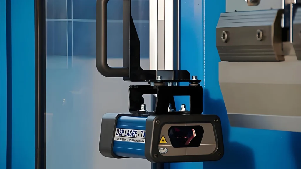
The DSP safety protection system is composed of two primary elements:.
TX (Transmitter) sensors, and
RX (Receiver) sensors
- These sensors are installed beneath the upper punch and work together to create a dynamic detection field that moves synchronously with the press brake ram. Unlike conventional safety light curtains that form a static detection plane, DSP systems generate a variable detection zone that changes according to ram position and machine speed.
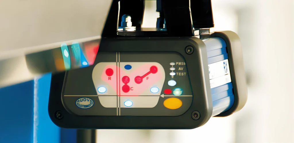
- This detection field is divided into three functional areas:
Front Detection Zone:.
Facing the operator, this zone is responsible for monitoring hand or body intrusion from the working side of the press brake.
Middle Detection Zone: Positioned slightly behind the punch tip, this zone directly protects the most dangerous point where bending occurs.
Rear Detection Zone: Oriented toward the back of the machine, this zone prevents unintended interference from rear access or machine components.
By dividing the detection area in this way, DSP systems achieve 360-degree monitoring of the press brake’s critical working region. This design ensures that safety is maintained without unnecessarily restricting normal production workflows. 1.2 Dynamic Synchronization with the Ram.
One of the most important technical characteristics of DSP press brake safety protection is its dynamic synchronization with the upper ram. As the ram moves up or down, the detection zone follows precisely, maintaining a consistent safety distance relative to the tooling.
This dynamic behavior allows the system to:
Maintain protection even during fast approach speeds.
Reduce unnecessary stops caused by irrelevant obstructions
- Adapt automatically to different tool heights and setups
- For fabricators handling frequent tool changes or short production runs, this adaptability significantly improves efficiency while maintaining a high safety level.
- 2. Full Activation Detection Mode: Balancing Safety and Productivity
In most standard bending operations, the DSP system operates in Full Activation Detection Mode, which provides the highest level of safety coverage.
2.1 Comprehensive Monitoring Throughout the Stroke
hen full activation mode is enabled, all detection zones—front, middle, and rear—remain active throughout the working cycle. This ensures that any intrusion into the protected area is immediately detected, triggering a safety response before an accident can occur.
During the fast approach phase, the DSP system continues to monitor the working area. If a hand or object enters the detection zone, the OSSD (Output Signal Switching Device) output switches to OFF, interrupting the fast downward movement of the ram.
This continuous monitoring is particularly important in high-mix, low-volume production environments, where operators frequently reposition parts and adjust setups.
2.2 Intelligent Suppression Near Material Contact.
A common challenge with optical safety systems is unintended triggering when the workpiece itself enters the detection field. DSP systems address this issue through intelligent signal suppression.
As the upper punch approaches the sheet metal, the material naturally blocks part of the middle detection zone. Instead of causing an unnecessary stop, the DSP system automatically suppresses the OSSD OFF signal at this moment. This allows the press brake to continue into the bending phase without interruption.
At the PCV (Point of Change in Velocity), the ram speed is reduced to below 10 mm/s, ensuring safe, controlled bending while maintaining productivity. This seamless transition between safety enforcement and process continuation is a defining feature of modern press brake safety technology.
2.3 Hierarchical Control Logic.
Another key aspect of DSP operation is the hierarchy of control signals. Once the speed reduction signal is activated, it overrides any OFF commands coming from outputs that only control the fast approach hydraulic circuit.
In practical terms, this means:
Safety remains active during high-risk phases.
Bending can proceed smoothly once the machine enters the controlled speed zone
- False stops are minimized
- For operators, this results in a more predictable and efficient bending process without compromising safety.
- 3. Special Operating Modes for Complex Bending Applications
While full activation mode is suitable for most applications, certain bending tasks require additional flexibility. DSP systems offer alternative operating modes to address these challenges.
3.1 Mode 2: Controlled Operation with Obstructed Detection Zones
When bending small parts, narrow flanges, or complex geometries, the standard safety configuration may prevent normal operation. In these cases, Operating Mode 2 provides a practical solution.
In this mode, selected front and rear detection zones are intentionally masked. Even if these masked zones are obstructed, the press brake can continue its fast closing movement until it reaches the PCV.
However, safety is not compromised. The middle detection zone remains fully active, ensuring that any intrusion near the punch tip immediately stops the machine. This selective protection strategy allows operators to handle difficult parts without bypassing safety devices or using unsafe manual methods.
3.2 Restoring Normal Operation Automatically.
Once the obstruction is removed and the bending cycle is completed, the system automatically restores full detection functionality. There is no need for manual resets or complex reconfiguration, reducing the risk of human error.
From a production perspective, this mode minimizes downtime while still complying with press brake safety regulations.
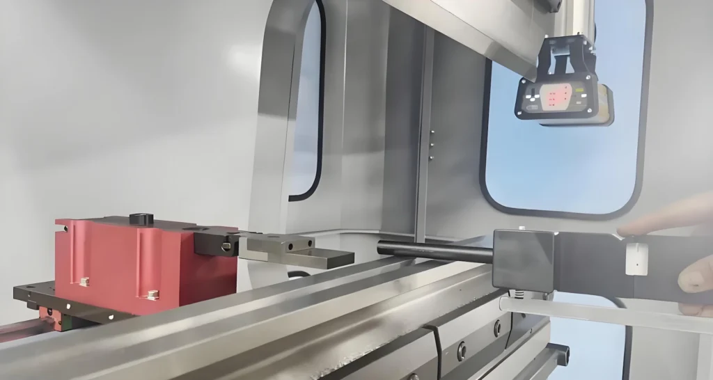
4. Importance of Rear Detection Zone Masking.
In real-world production environments, safety systems must coexist with other machine components. One common issue arises when the rear detection zone interferes with the backgauge system.
4.1 Mode 3: Eliminating Unnecessary Interference
Operating Mode 3 is designed specifically for situations where rear-side monitoring is unnecessary or counterproductive. In this mode, the rear detection zone is disabled, while the front and middle zones remain fully active.
This configuration prevents unwanted machine stops caused by backgauge movement while ensuring that the operator’s working area remains protected.
4.2 Maintaining Compliance and Safety.
Importantly, Mode 3 does not reduce overall safety performance when applied correctly. Since operators do not access the rear side during normal operation, maintaining protection in the front and central zones is sufficient to meet safety requirements.
Manufacturers often implement Mode 3 after conducting a formal risk assessment, ensuring compliance with international press brake safety standards.
5. Practical Benefits for Fabricators.
Implementing DSP press brake safety protection offers tangible advantages beyond regulatory compliance.
First, it significantly reduces the risk of serious hand injuries, protecting skilled operators and lowering insurance and compensation costs. Second, it improves productivity by allowing higher approach speeds and fewer false stops. Third, it simplifies operator training, as safety functions are largely automated and intuitive.
For manufacturers aiming to modernize their press brakes, DSP systems represent a cost-effective safety upgrade that enhances both protection and performance.
Press brake safety is no longer a trade-off between protection and productivity. With advanced DSP safety protection systems, manufacturers can achieve both. By dynamically monitoring the bending zone, intelligently managing detection signals, and offering flexible operating modes, DSP technology provides a comprehensive solution to modern press brake safety challenges.
For companies seeking to improve workplace safety, meet global compliance standards, and maintain competitive production efficiency, investing in a modern press brake safety system is not just a regulatory requirement—it is a strategic decision.
Press brake maintenance and repair should be viewed as an ongoing process rather than a reaction to failure. Proper lubrication, careful hydraulic system management, and regular mechanical inspection form the foundation of reliable machine operation. These practices not only reduce downtime but also help maintain consistent bending accuracy over the machine’s service life.
DSP_LASER_r1_8_ENG.
Accordion. Open links with Enter or Space, close with Escape, and navigate with Arrow Keys.
Read more about Principle and Function of Press Brake Safety Protection System
Q1: What is press brake safety protection?
Press brake safety protection refers to systems designed to prevent operator injury during bending operations, typically using sensors, light curtains, or dynamic detection technology.
Q2: How does DSP differ from traditional light curtains?
Unlike static light curtains, DSP systems create a dynamic detection zone that moves with the ram, offering better protection and fewer false stops.
Q3: Is DSP press brake safety suitable for small or complex parts?
Yes. Special operating modes allow controlled operation while maintaining protection near the punch tip.
Q4: Does masking detection zones reduce safety?
When applied correctly and based on risk assessment, selective masking improves usability without compromising operator safety.
Q5: Can DSP systems help meet CE and ISO safety standards?
Yes. DSP press brake safety systems are designed to support compliance with major international safety regulations.

V-Grooving Machine
- Press Brake
- Laser Cutting Machine
- Shearing Machine
- Press Brake Safety Precautions: Complete Guide for Safe Operation and Maintenance
- Hydraulic Press Machine
- Read more about Practical Methods for Press Brake Accuracy with Long Term Precision
- Rolling Machine
- Ironworker
- Press Brake Tooling
- Machinery Accessories